Revealing Hidden Surfaces Using Clip Planes
Clip planes allow you to slice through the rendered objects using plane sections and hide the sliced portion on one side.
Six clip planes are provided within the node. By default, Plane 1 and Plane 2 lie on the YZ plane with the plane normal being in the X direction for Plane 1 and in the -X direction for Plane 2. Similarly, Plane 3 and Plane 4 lie on the XZ plane, and Plane 5 and Plane 6 lie on the XY plane.
Each active clip plane hides any portion of the model that lies behind it (as defined by the positive normal).
- To activate a clip plane, select the node and activate Enabled.
-
Control the position of the plane using either of the following
techniques:
- Link the clip plane to a local coordinate system by making a selection
in the Coordinate System property, and
thus simplify your direction calculation by changing the frame of
reference.
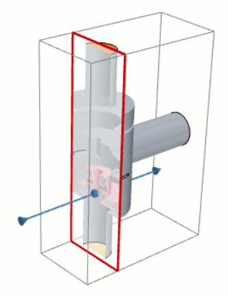
For example, suppose you have a simulation with a pipe, which is not aligned to the laboratory coordinate system. You can align the clip plane with the pipe axis to see the mesh definition on the inside.
- Use the interactive tool in the scene display, similar to the one used
for the plane section derived part, to adjust the position of the clip
plane:
- To move the position of the clip plane along the normal direction
defined by the arrow:
- While the [clip plane] node is highlighted, in the graphics window, position the mouse pointer anywhere within the area surrounded by the red border.
- Click and drag the mouse pointer backwards or forwards in a direction parallel to the normal vector.
- To change the orientation of the clip plane, do the same action as in the previous step, but position the mouse pointer over the direction arrow instead. When you click and drag the arrow, the direction of the plane changes accordingly.
- To move the position of the clip plane along the normal direction
defined by the arrow:
In the graphics window, the portion of the rendered objects behind the clip plane becomes invisible.
- Link the clip plane to a local coordinate system by making a selection
in the Coordinate System property, and
thus simplify your direction calculation by changing the frame of
reference.
- To switch the portion of the rendered objects that is hidden, right-click the node(s) and select Invert Plane.
-
If you want to reset all clip planes to their default position and orientation,
right-click the Clip Planes node and select
Reset Planes.
When you reset clip planes, they are also deactivated.