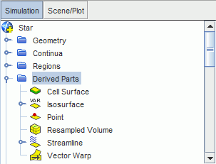
Accessing Solution Data through Derived Parts
Although Simcenter STAR-CCM+ can display, analyze, and report simulation data on regions, boundaries, and parts, there are many cases when you want to access data in other entities of the solution space. Derived parts provide a mechanism for defining additional entities on which you can access solution data.
A part that is based on another part is known as a derived part. A derived part is created using one or more other parts as parent parts, or inputs, and it is dependent on these parent parts. If any of the parent parts change, all parts depending on those parent parts are automatically recalculated and redisplayed to reflect the change.
For example, consider the following: An isosurface of pressure is created in a three-dimensional region and a plane-section is created from the isosurface resulting in a curve in space. The parent of a plane is the isosurface, and the parent of an isosurface is the three-dimensional region. If the region is modified somehow, for instance by either the mesh or the solution changing, first the isosurface is recalculated, and the plane follows. In this way, consistency is maintained for all parts.

You can add and edit any of various derived parts and use them to examine solution data. Creating and editing can be done visually using the powerful in-place dialog. A derived part gets its data when you select input (parent) parts for it. Certain derived parts can be defined using local coordinate systems. Various types of derived parts can be split based on individual input parts, or according to subsets of values (see Splitting Derived Parts by Input and by Value).
You can control the naming of derived parts. If a derived part is no longer needed, it can be deleted. You can also copy a derived part to use it as a starting point for a new part, or to create a deep copy for use in a different simulation. It is possible to manipulate several of these derived parts visually using tools. Some derived parts use data from an external file. You can also export data that the derived parts extract. When you group a set of derived parts, you can highlight all those parts in a scene by right-clicking the group manager node and selecting Highlight.
Derived Part Types
| Cell Surface | Represents all the cells adjacent to or intersected by a specified input part. |
| Isosurface | Surface over which a scalar function has a constant value. |
| Probe | Takes samples of data in a region based on coordinates or intervals that you specify. |
| Section | Based on planes or geometrical shapes, which can be cut through one or more volumes or surfaces. |
| Streamline | Represents particle paths. |
| Constrained Streamline | Represents particle paths that are constrained to lie in a surface. |
| Vortex Core | Detects vortex cores in a flow field. |
| Separation/Attachment Line | Detects where flow separates from or attaches to a surface. |
| Threshold | Isolates a group of cells based on their relationship to specified scalar values. |
| (m’, theta) warp | Unwraps results to a flat plane. |
| Resampled Volume | Volume rendering is used to display volumetric objects that are defined in a 3D domain. |
| Warp | Moves the point coordinates on the surfaces of its input parts along a selected vector multiplied by a scale factor (vector warp), or along the point normal vectors by an amount equal to a specified scalar times a scale factor (scalar warp). |
| Average Surface | Evaluates the circumferential average or weighted circumferential average of a scalar or vector field function over the selected 3D regions or parts with respect to the selected axisymmetric parameterization. |
| Average Profile | Evaluates the circumferential average of a scalar or vector field over the selected input surfaces of revolution with respect to the selected axisymmetric parameterization. |