Directed Meshing
Directed meshing is a method for generating high quality swept meshes on geometries in Simcenter STAR-CCM+. The method operates by sweeping a mesh from the surfaces of a geometry through its volume onto a facing target surface.
Inputs to directed meshing include geometry with CAD data, partial CAD data, and no CAD (such as .stl imports, discrete surfaces, or the result of surface wrapping).
You can use a mesh that is created using the directed mesh tool in any Simcenter STAR-CCM+ analysis, along with meshes created using other methods. Directed meshing is ideal for meshing FV (Finite Volume) fluid flow simulations as it provides a structured mesh in the axial direction. When using the Solid Stress model for FE (Finite Element) stress analysis, you can use the directed mesher to generate 3D hexahedral elements. For more information on the mesh requirements for FE simulations, see Finite Element Mesh: Requirements and Guidelines.
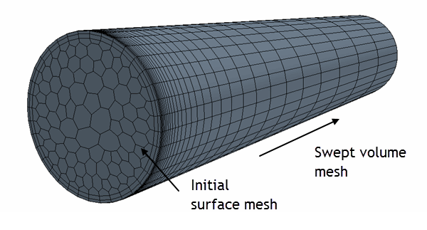
The directed mesh feature gives you a high degree of control when generating a volume mesh. For example, you can create hexahedral meshes for highly irregular geometries in one operation. You can also create meshes that are flow-aligned, resulting in better accuracy within solvers.
The sweep paths can be linear or curved and the cross section may change in size and shape. Source and target surfaces do not need to be planar.
You can use the directed meshing feature on geometry parts whose surfaces are designated as:
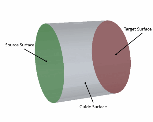
- Source surfaces, where you generate the initial surface mesh
- Target surfaces, where the directed mesh ends
- Guide surfaces along which the mesher sweeps the initial mesh from the source surfaces to the target surface
It is also possible to create internal mesh faces using empty part surfaces (1-1 meshing only).
| 注 | You can create and select settings for a directed-meshing operation node, but you must assign parts to regions before executing it. |
There are two directed meshing strategies:
- Many sources to one target (M-1) - Meshes from multiple source faces are swept through the volume to a single target surface in one operation. M-1 allows you to mesh many-sided part geometries, with source surfaces at different layers of the sweep. Some examples are shown below.
- One source to one target (1-1) - A directed mesh is produced for each part collection. If necessary, you can split-up complex parts so as to provide the necessary guide surfaces.
M-1 is an automated approach, whereby Simcenter STAR-CCM+ submaps the guide surfaces to enable the mesh to be swept through the volume. There are some restrictions related to the M-1 approach that are discussed in context within the following sections. In some instances, it will be prudent to mesh sets of parts individually, using a 1-1 approach.
You can create source meshes for the Directed Mesh operation in several ways:
-
Creating patches on the surfaces and defining quad cells within the patches (Note: 1-1 directed meshing only) . See Creating a Source Mesh Using Patches.
-
Extracting meshes from existing volume meshes on which the surfaces lie. See Creating a Source Mesh Using an Existing Mesh.
-
Create 2D source meshes on which you can include prism layers. See Creating a 2D Source Mesh.
| 注 | You cannot use different mesh types in combination for the same source surface of a part. Patch meshing is not supported for M-1 meshing. |
Each source surface mesh is associated with a volume mesh distribution that is used to generate the final volume mesh.
Currently, the smoothing algorithms within the mesher aims to replicate the mesh on the source surface onto the target surface whenever possible. When source or target surfaces are non-planar, this process can generate poor quality and negative volume cells—especially when using M-1. In some cases (such as for standard cube and cylinder shapes), it is not necessary to smooth the target surface mesh. You can deactivate this option. See Directed Meshing Properties: Connected Parts - Part Properties.
Simcenter STAR-CCM+ can perform directed meshing when there are spanning faces on both source and target surfaces. However, if the target surface has multiple CAD faces, and the edges between those CAD faces are not marked as features, these edges are not resolved and, in effect, there is only a single target surface and the directed mesher may fail.
Examples showing directed mesher sweep capabilities:
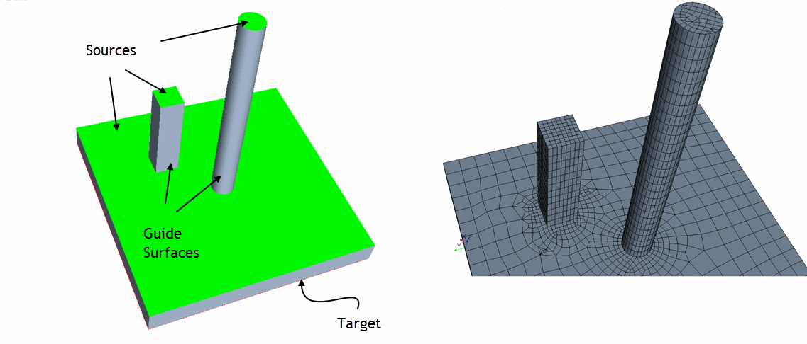
- Three planar sources at different sweep layers swept to a single target (M-1). Here, the extended pin surfaces are unconnected:
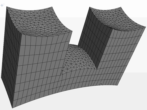
- Part with 3 curved triangular source meshes and curved target:
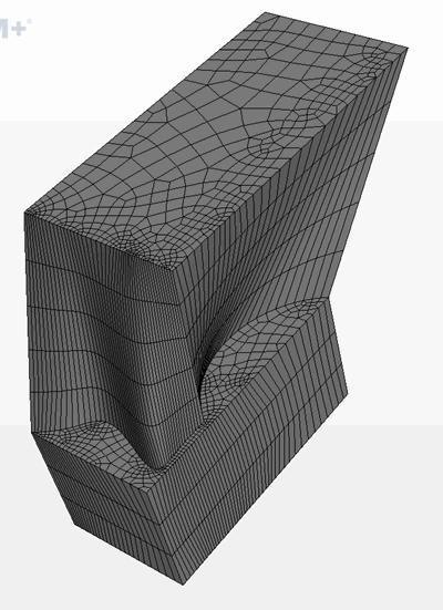
- Part with quadrilateral source meshes, loft and curved submapped surfaces in the sweep direction:
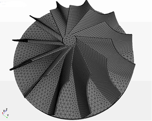
- Impeller with curved sweep in two planes:
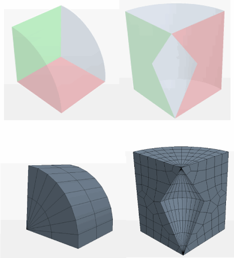
- Rotational sweeps about a common edge or connected vertices
Creating Directed Meshes in Simcenter STAR-CCM+
The subsequent sections provide information on setting up and generating directed meshes in Simcenter STAR-CCM+.