Mesh Requirements and Guidelines
Finite element stress analyses in Simcenter STAR-CCM+ require a mesh of 3D solid elements generated using parts-based mesh operations, or imported as a CAE model. Simcenter STAR-CCM+ supports hexahedral, tetrahedral, wedge, and pyramid element types. Each type is available without mid-side nodes (linear element), or with mid-side nodes (quadratic element).
Element Type Reference
In Simcenter STAR-CCM+, mesh operations generate linear elements by default. You can achieve quadratic elements by using the Mid-side Vertex Option, which adds mid-side nodes as interpolates of the corner nodes that are generated by the mesh operations. The Mid-side Vertex Option is available as a physics condition for the solid region. For more information, see Region Settings.
| Element Topology | Element name | Diagram | Nodes | Faces | Edges | Element Type FF Identifier | |
|---|---|---|---|---|---|---|---|
| Tetrahedron | Linear | Tet4 | 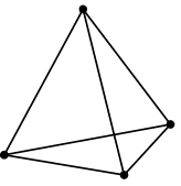 |
4 | 4 | 6 | 10 |
| Quadratic | Tet10 | 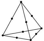 |
10 | 4 | 6 | 24 | |
| Wedge | Linear | Wedge6 |
 |
6 | 5 | 9 | 13 |
| Quadratic | Wedge15 | 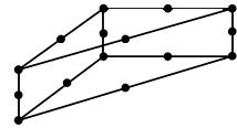 |
15 | 5 | 9 | 26 | |
| Hexahedron | Linear | Hex8 | 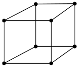 |
8 | 6 | 12 | 12 |
| Quadratic | Hex20 | 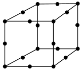 |
20 | 6 | 12 | 25 | |
| Pyramid | Linear | Pyramid5 | 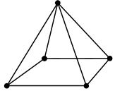 |
5 | 5 | 8 | 14 |
| Quadratic | Pyramid13 | 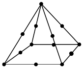 |
13 | 5 | 8 | 27 | |
In general, quadratic elements are more accurate than linear elements, but increase the simulation degrees of freedom, and therefore, the computation cost. Linear elements can give a reasonably accurate solution in structural analyses where stresses are not varying rapidly across the region. However, linear elements of tetrahedral (Tet4), wedge (Wedge6), and pyramid (Pyramid5) topologies can cause locking, that is, the computed displacements can be orders of magnitude smaller than expected. These elements are particularly "stiff" in problems with thin members under bending loads, where the element aspect ratios can be large.
- The stiffness matrix is more compact. Therefore, Simcenter STAR-CCM+ requires less memory to store and factorize the matrix.
- The level of accuracy is high even for cases with thin members under bending loads, where the element aspect ratio is large.
- These elements require fewer integration points, and hence fewer operations, to evaluate the stiffness matrix and the residuals.
Not all geometries can be easily meshed with hexahedra. When a geometry requires elements of other types, or a mix of elements with different topologies, it is important to add mid-side nodes to use quadratic order elements. In general, pyramids are not accurate and are acceptable only as transition elements, far from areas where large stresses are expected.
Steps for generating element topologies appropriate to finite element stress analysis are provided within the section, 应力分析的常规工作流.
Mesh Refinement
- Fillets and curved edges
- Re-entrant corners
- Holes
- Cracks
- Welded surfaces which intersect free surfaces
For example, a fillet between two parts which are joined at 90° requires at least 4 elements to span the quarter circle of the radius. A hole should have at least 16 elements to span the circumference. Near the root of a crack, the elements must be highly refined in a region about 2 crack lengths near the surface, with most of the refinement near the root and coarsening as the distance from the crack root increases. When using an elastic model with a crack, the matrix is singular, that is, the stresses are infinite at the tip of the crack, regardless of the mesh resolution. Here the principles of Fracture Mechanics must be applied to assess the severity of the loads on the crack. These principles determine whether the loads on the crack tend to cause catastrophic failure or slowly grow the crack under cyclic loads.
Mesh Quality Metrics
Poor element quality can lead to a matrix which is ill-conditioned. The direct solvers are designed to accept some ill-conditioning but not without an overhead cost in time and memory.
Mesh Validity
A mesh containing invalid elements can lead to poor convergence, divergence, or a non-positive stiffness matrix, resulting in the finite element solution in that area to be incorrect or the problem being unsolvable. To find these invalid elements you can use the Fe Invalid Element Indicator field function. The finite element validity is checked automatically on all FEA simulations. The check is triggered when the simulation is initialized for the first time and every time the mesh geometry is changed. If invalid elements are discovered during this check a warning message is displayed in the output window.
Avoid invalid finite element cells where possible and where it is not possible take extra care when analyzing results in areas containing invalid elements.
It is also advisable for stress simulations with Nonlinear Geometry active, the solid displacement motion is activated for the non linear regions to detect invalid distorted elements.
Replacing the Mesh
When replacing an existing mesh with a new mesh, Simcenter STAR-CCM+ automatically interpolates any vertex data (such as Displacement), available on the existing mesh, to the new mesh vertices. For more information on the Replace Mesh operation, see Replacing A Mesh Region.
Thin Parts Under Bending Loads
For thin parts under bending, Hex8 elements are preferred. Hexahedral elements with mid-side nodes (Hex20) have better accuracy but at a cost of more memory and operations. Wedge elements with mid-side nodes (Wedge15) are also suitable when the geometry is sufficiently regular, so that a triangular surface mesh can be extruded through the thickness of the part to create wedges. For such geometries, this operation is done automatically when using the Thin Mesher with the Tetrahedral Mesher. However, in transitions from thick sections to thin sections these meshers can generate some pyramid elements, which are not suitable in areas with large stresses.
Thin parts under bending should have at least two aligned elements through the thickness. The number of elements through the thickness primarily affects the level of accuracy of the computed axial stress. Beam theory shows that the axial stress linearly varies from compressive to tensile along the neutral axis. Therefore, thin parts in bending that have the neutral axis in the center have high stress gradients. In these cases, higher order elements are more appropriate. However, the displacements due to bending loads are reasonably approximated with aligned Hex8, Hex20, or Wedge15 elements even with only one element through the thickness. This guideline assumes that the mesh resolution is sufficient in the plane of the thin part. Tet4 and Wedge6 elements are particularly poor in these situations, because they tend to be excessively stiff even when the aspect ratio of the elements is near unity. For Tet4 elements, it is particularly important to add mid-side nodes.
Finite Element Solid Shells Heat Transfer
In Simcenter STAR-CCM+, finite element solid shells are compatible with quadrilateral and triangular 2D linear elements (See H1 Lagrange Shape Functions). To produce the required 3D Wedge6 and Hex8 elements, the mid-surface of the 2D elements is discretized and the three dimensional geometry is obtained using shared vertex normal vectors. For heat transfer, the 3D solution is considered by using a linear temperature approximation across the shell thickness.
To enforce temperature continuity across the internal shell edge-to-edge interface, between joined shell parts, the Finite Element Solid Energy model adds additional constraints to the part by tying the degrees of freedom at the top and bottom surfaces across the interface.