2D Sketch Entity Reference
Sketches are comprised of sketch entities. The following table describes the 2D sketch entities that are available in 3D-CAD.
| Sketch Entity | Description and Procedure |
|---|---|
 (Point ) | A point is a single vertex. To create a point, click the location where you want to place it. 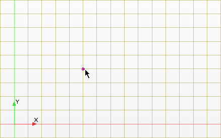 |
 (Line) | A line is a straight edge that is constructed from a start point and an end point. To create a line, you require two mouse clicks: the first defines the start point, the second defines the end point. To create multiple lines, continue to define points after defining the end point of the first line. Click <Esc> to exit the line tool 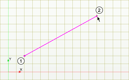 |
 (Rectangle) | A rectangle is constrained to be aligned with the X and Y-axis directions on the sketch plane. To create a rectangle, you require two mouse clicks: one to define the location of the first corner and the second to define the opposite corner. Rectangles are automatically constrained so that one set of opposite lines is horizontal, and the other is vertical. 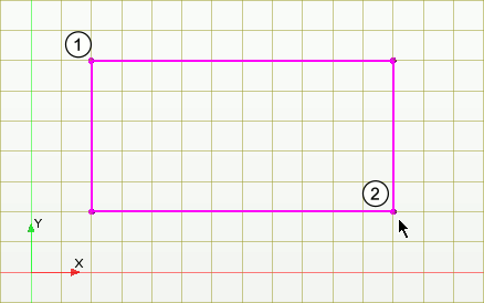 |
 (Center Point Rectangle) | A center point rectangle is created around a center point and maintains its symmetry around the selected point. To create a center point rectangle, you require two clicks: the first defines the center point and the second defines the length and width of the rectangle. The rectangle is automatically created with the constraints required for symmetry. 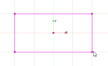 |
 (Three-Point Rectangle) | A three-point rectangle can be oriented in any direction. To create this type of rectangle, you require three clicks: the first two clicks set the length and orientation of the rectangle; the third click sets the width. The rectangle is automatically constrained with perpendicular and parallel constraints. 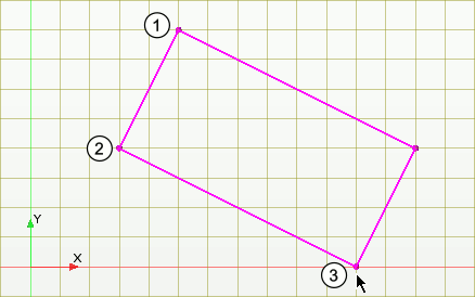 |
 (Circle) | To define a circle, you require two mouse clicks: one to set the center of the circle, and the other to set the radius of the circle. 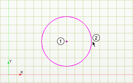 |
 (Center-Point Circular Arc) | A circular arc is a segment of a circle. To create a center-point circular arc, you require three mouse clicks: one to define the center of the arc, and two further clicks to set the start point and the end point. The arc is drawn anti-clockwise from the start point to the end point. Simcenter STAR-CCM+ provides a function that converts and arc into its complement. This function is useful when the original arc is drawn in the opposite direction to the one that you require. See Converting an Arc Into its Complement. 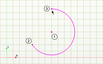 |
 (Three-Point Circular Arc) | A circular arc is a segment of a circle. To create a three-point circular arc, you require three mouse clicks: the first two clicks set the start and end points of the arc, and the third click sets the radius of the arc. Simcenter STAR-CCM+ provides a function that converts and arc into its complement. This function is useful when the original arc is drawn in the opposite direction to the one that you require. See Converting an Arc Into its Complement. 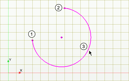 |
 (Ellipse) | An ellipse is a closed loop in the shape of an oval or flattened circle. To create an ellipse, you require three mouse clicks: one to set the center of the ellipse, followed by two further clicks to define the minor and major radii. You can create an elliptical arc by splitting and trimming an ellipse. It is possible to apply minor and major radius dimensions by right-clicking on the sketch and selecting Apply Minor Radius or Apply Major Radius. 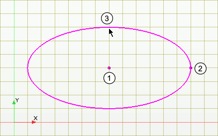 |
 (Spline) | A spline is a smooth curve that is composed from a series of points (called spline points). To create a spline, you require a minimum of three mouse clicks, which set the position of each spline point. You can add or remove points from the spline, as well as edit the position of each spline point individually. See Splines. 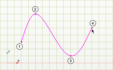 |
 (Create Equation Based Curve) (Create Equation Based Curve) | Allows you to create a curve defined by equations for the x and y components. See 在 3D-CAD 模型上创建草图. |