Use 3D sketching to create sketches whose entities are constructed from points and lines located anywhere in 3D space. These 3D sketches can then be used to build or modify complex three-dimensional shapes.
In 2D sketching you are restricted to two dimensions on a plane; 3D sketching is not restricted to any plane. With 3D sketching you can create advanced lofts with guide wires, complex surfaces to fill gaps or holes with, and allow for a broader range of parametric surfaces for design exploration. You can also use 3D sketching to edit imported 3D curves. For an example where you can reference existing bodies, see Offsetting Entities in a 3D Sketch.
To create a 3D sketch:
- Enter the 3D sketching module:
- Right-click the Features node and select Create 3D Sketch.
- Right-click a CAD edge in the 3D-CAD View scene and select 3D Sketch From Edges.
In the
3D-CAD View scene, a grid appears having a triad at its center. The triad indicates the X, Y, and Z directions and allows you to move sketch entities and choose the plane on which to draw sketch entities.
The 3D sketch panel appears on the left hand side of the window. This panel contains the sketch tools and display options. For more information about the display options, see Sketch Display Options.
- To change the current coordinate system in the 3D sketch:
- At the top of the Sketch3D panel, click inside the Coordinate System field at the top of the 3D Sketch panel.
- In the graphics window, select the triad belonging to the target reference coordinate system.
The triad axes align with the axes of the local coordinate system to confirm that the change occurred.
Creating 3D curves generally requires you to add one or more points to the sketch (unless you are satisfied with any existing edges that you chose before entering the 3D sketch mode).
- To add a single point within the 3D sketch:
- On the Sketch3D Edit panel, click Create Point.
By default, within
Display Options, the three options
Pick on Plane,
Pick on Geometry, and
Show or Hide Triad are activated. The options
Pick on Plane and
Pick on Geometry control what happens as you move the mouse pointer around in the graphics window.
 (Pick on Plane) means that when the mouse pointer is positioned on white space in the graphics window, coordinate positioning lines extend from the origin of the active sketch plane. You can change the active sketch plane using the triad.
 (Pick on Geometry) means that when the mouse pointer moves over edges or faces of existing geometry, the nearest edge or face changes color to show that it is the active location for the point. For an edge, the yellow point is constrained along the highlighted edge for as long as the mouse pointer remains close to the edge.
 (Show or Hide Triad) allows you to hide the triad. Normally, you are advised to keep the triad visible as the triad allows you to switch between coordinate planes when
  (Pick on Plane) is activated.
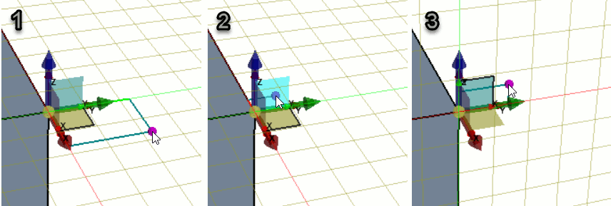
- To change the active plane on which to create a point, position the mouse pointer over one of the three plane selectors that surround the triad origin. When the plane selector changes color, click using the left mouse button.
In the example below, the active plane is changed from the XY plane in (1), to the ZY plane in (3). Clicking on the plane ZY plane selector in (2) makes this change.
- Position the mouse pointer over the location at which you wish to create a point, and click using the left mouse button.
- To draw points, lines, or curves in 3D space:
- In the Sketch3D panel, click the relevant button for the tool that you want to use.
The tools in the 3D sketch module behave in the same way as their 2D counterparts, except that in 3D sketching, you can draw in all three dimensions. See
3D 草图实体.
For points,
Simcenter STAR-CCM+ provides an additional menu in the sketch panel that allows you to control the way in which you define points. For example, you can enter coordinates directly, or else specify an offset from an existing point. See
Offsetting Entities in a 3D Sketch.
- In the graphics window, move the mouse pointer to the first location and click.
When sketching in 3D, entities that you draw in the graphics window are constrained to the active plane. As you move the mouse pointer around the scene, the two dimensions that define the current location are projected to the mouse pointer.
- If you want to add further points on the same plane, move the mouse pointer to that location and click.
- If you want to add the next point on a different plane, first click the desired plane on the central triad. This action does not end the point placement, but switches to the target plane.
As you move the mouse over the plane, it becomes highlighted to indicate that clicking here will result in the plane switching rather than placing a point in 3D space.
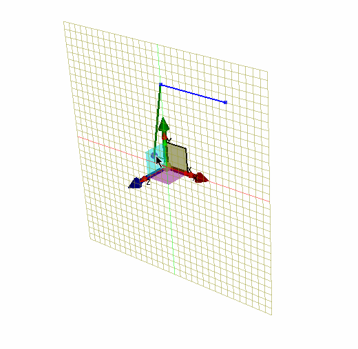
The sketch grid switches to the chosen plane. You can switch planes/direction as many times as needed while a sketch tool is active.
- Move the mouse pointer to the next location and click.
- Continue to add as many points as you require, on whichever planes are appropriate. You can switch planes on the triad as many times as you wish.
- To stop drawing and exit the active sketch tool, press the <Esc> key.
- To draw on the surface of an existing body:
- In the Sketch3D panel, click
 (Line on Surface) or
  (Spline on Surface).
 - To limit the placement of points and sketches to geometry surfaces only, deactivate the
 (Pick on Plane) option and activate the
  (Pick on Geometry) option.
 - In the graphics window, move the mouse cursor over a surface on an existing body.
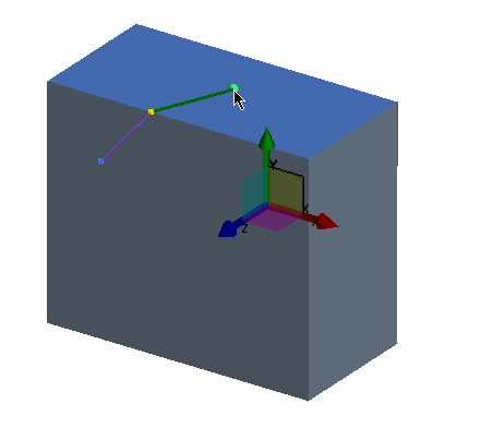
The surface becomes highlighted in blue to indicate that it is a valid surface on which you can create points.
- Click the first point on the surface.
- Move the mouse pointer over an edge and click.
The edge becomes highlighted in yellow to indicate that it is an edge you can interact with.
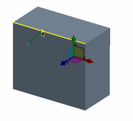
- If you are using the
 (Line on Surface) tool, you can move the mouse pointer over the adjacent face, next to the edge that you placed a point on, and click to place the point on that face.
 | 注 | When using the  (Line on Surface) tool, you can draw a line that spans multiple faces only after you place a point on the adjoining edge. You cannot span multiple surfaces using the (Line on Surface) tool, you can draw a line that spans multiple faces only after you place a point on the adjoining edge. You cannot span multiple surfaces using the  (Spline on Surface) tool. (Spline on Surface) tool. |
- Sketch the remaining points on the surface.
- To stop drawing and exit the active sketch tool, press the <Esc> key.
While drawing a 3D sketch, you can snap to points on existing bodies. You can also bring existing points and edges from other bodies into the 3D sketch by converting them to 3D sketch entities.
- To convert points or edges on an existing body, right-click on the point or edge and select Convert to 3D Entities. For edges, you can alternatively choose Convert to 3D Entities As Construction, which brings the edge into the 3D sketch as a construction line. To project sketch as construction entities, select Convert to 3D Entities As Construction.
The selections are converted to 3D sketch entities and are displayed in a different color to the sketch entities.
- To duplicate sketch entities, including converted entities, right-click the sketch entity and select Duplicate.
Duplicated entities are not associated with the original entity, which means that if you modify the original entity, such as the shape of a box whose edge you duplicated, the duplicate is unchanged.
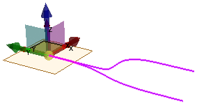
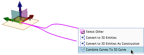
- To create a 3D curve from two existing 2D curves:
- Multi-select two existing 2D curves.
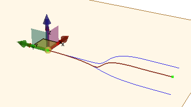
- Right-click on one of the 2D curves and select Combine Curves to 3D Curve.
The 3D curve appears in dark brown. You can use the 3D curve in a swept or loft operation.
- To convert any point or edge on an existing body to a 3D sketch:
- Navigate to the features toolbar and select .
- Click the desired points or edges you want to convert to a 3D sketch.
- Click OK to confirm selection and create a 3D sketch.
Changing the position of the 2D sketch points also modifies the 3D sketch.
- To move a point that you have already placed in 3D space:
- In the graphics window, click the point that you want to move.
The triad snaps to the selected point.
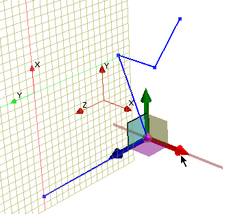
- Move the mouse pointer over the desired triad direction arrow and click and drag the arrow.
As you move the mouse pointer over each direction arrow on the triad, these become highlighted and display a projection line (shown for the red triad axis in the following example) if you can move the point. If you cannot move the point due to some constraint, no projection appears on the triad axis.
- Click and drag the arrow in the direction that you want to move the point.
The 3D sketch updates as you move the point.
- If necessary do the same for the other two directions.
- To move multiple points together:
- In the 3D-CAD View scene, press and hold the <Ctrl> key and select the points that you want to move.
The triad appears at the mean geometric position for the selected points.
- Move the mouse pointer over the desired triad direction arrow and click and drag the arrow.
The selected points move together and maintain their position with respect to each other.
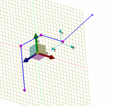
- To move points precisely, click a point in the graphics window and modify the point coordinates in the Edit Point panel.
- To change the coordinate system of an existing point in the 3D sketch:
- In the 3D-CAD View, select the point that you want to modify.
- In the Edit Point group box, click inside the Coordinate System field at the top of the 3D Sketch panel.
- Click on the visual representation for the local coordinate system in the 3D-CAD View scene.
The triad axes align with the axes of the local coordinate system to confirm that the change occurred. The entry in the Coordinate System field also updates to show the change.
- To create a helix sketch:
- First create a line (or curve) within the 3D sketch that defines the central path for the helix. The helix begins at either end point of this line.
- In the Sketch3D panel, click
 (Create Helix).
 - In the graphics window, select the line or spline curve for the Curve to Define Axis.
- To define the plane from which start and end angles are measured, click within Point to Define Plane and select an existing point in the graphics window.
If no point exists, cancel the helix operation, create a point on a planar surface or edge using Create Point, and then start the helix operation again.
A preview of the helix sketch appears in the
3D-CAD View scene.
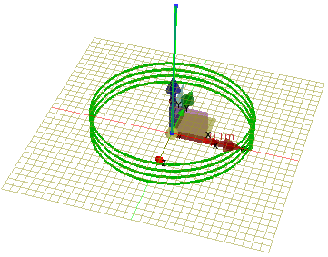
- Continue by setting the Helix Radius and Start Angle.
- Within Helix Type, choose between a helix defined by the overall number of turns, or one defined by the end angle (relative to the plane defined by the chosen point). Set the number of Turns or End Angle according to your choice.
- Finalize the helix by setting the Axial Pitch (distance between each turn) and the Radial Pitch (only required for a conical or spiral helix).
By setting the Axial Pitch to zero, and providing a non-zero Radial Pitch, you can create a spiral curve rather than a helix.
You can define curves directly by providing their equations.
- To create an equation based curve:
- Define the required interval design parameters and scalar design parameters for the equations (see Creating a New Design Parameter).
For each component of the curve, define the equation directly in the
Equation Base Curve dialog. The equations specified for the x, y, and z components must contain an interval design parameter. For more information, see
Interval Design Parameters. You must use the interval parameters directly in the equations. The equation is not defined if the interval design parameter is defined in a separate design parameter.
- In the Sketch3D panel, click
 (Create Equation Based Curves).
 - In the Create Equation Based Curve dialog, specify the X, Y, Z component equations using the Simcenter STAR-CCM+ expression syntax as well as the Interpolation Points.
The interval range specified in the interval design parameter is split according to the number of
Interpolation Points you specify. For each interpolation point the x, y, and z coordinates are calculated using the equations specified. If you use a higher number of interpolation points,
Simcenter STAR-CCM+ defines the curve with greater accuracy. Between each point of the curve a spline interpolation is used to connect the points.
The x, y, and z component equations can be exposed by clicking  (Expose Design Parameter). For more information, see Exposing a Parameter. Do not use the exposed parameter in any other equation or scalar design parameter.
- If required, deactivate Zero Curvature At End Points.
- To edit the curve, in the 3D-CAD View scene, right-click the curve and select Edit Equation Curve.
- To complete the 3D sketch, click OK.
A 3DCurve feature is added to the 3D-CAD feature tree.
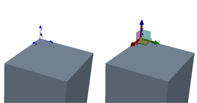 The triad axes align with the axes of the local coordinate system to confirm that the change occurred.
 (
( (
( (
(

 (
( (
(

 (
(
 (
( (
(