Engine
The following right-click actions and dialogs are available for Engine Parts in Simcenter STAR-CCM+ In-cylinder.
Engine Right-Click Actions
| Object | Right-Click Action |
|---|---|
| Engine |
|
 [engine part] [engine part] |
|
 [engine part surface] (for cylinder / cylinder sector, plenum, and valves) [engine part surface] (for cylinder / cylinder sector, plenum, and valves) |
|
 [nozzle] (for injector) [nozzle] (for injector) |
|
Engine Parts Creation Dialog
| Engine Configuration | |
|---|---|
| Intake Valve(s) | Displays the auto-calculated number of imported intake and exhaust valves. |
| Exhaust Valve(s) | |
| Strokes | Specifies the cycle length. The following options are available:
|
| Part Creation Options | |
|---|---|
| Keep feature edges (deg) | Creates part curves on named edges whose attached faces form an angle that is sharper than the specified value. Part curves are used to define edges and surface features from the surface geometry all the way through to the final volume mesh. Without part curves, such edges are not preserved. See Part Surfaces and Part Curves. The default value is 5. A value of 0 creates part curves on all the edges of the geometry. |
| Engine Symmetry | |
|---|---|
| Half Model | When On, creates a half model from a symmetric geometry.
|
Cylinder Dialog
- Name
- Specifies the name of the cylinder under which it is stored in the tree.
| Initial Conditions | |
|---|---|
| Turbulence Specification (for a RANS simulation) | Controls how you define the initial turbulence profile for the cylinder and the ports. The following options are available:
The corresponding value nodes become available in the Cylinder and Intake / Exhaust Port [n] group boxes. For more information, see K-Epsilon Initial Conditions Reference. |
| Cylinder |
|
| Intake / Exhaust Port [n] (not for cylinder sector models) | |
| Motion | ||
|---|---|---|
| Engine Geometry |
| |
| ||
| ||
Valve Dialog
- Name
- Specifies the name of the valve under which it is stored in the tree.
| Motion | |||
|---|---|---|---|
| Valve Lift File | Specifies the table that describes the valve lift in mm as a function of crank angle in deg. Import allows you to import a table of one of the following file formats: *.csv, *.txt, or *.dat.
| ||
| Lash | Defines the play resulting from loose connections between the rocker arm and the valve stem. When the valve lash is zero, the valve lift profile shows smooth opening and closing ramps. Increasing the valve lash moves down the valve lift profile. Typically, the valve lash ranges between 0.1 mm and 0.25 mm. Example: Setting lash to 0.25 mm. 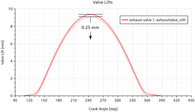
| ||
| Profile Anchor / Cycle Anchor | The Profile Anchor sets an angular position in the defined lift profile. The Cycle Anchor sets the angular position in the engine cycle to which you want to move the profile anchor. Example: Setting the profile anchor to 107.0 deg and the cycle anchor to 150.0 deg. 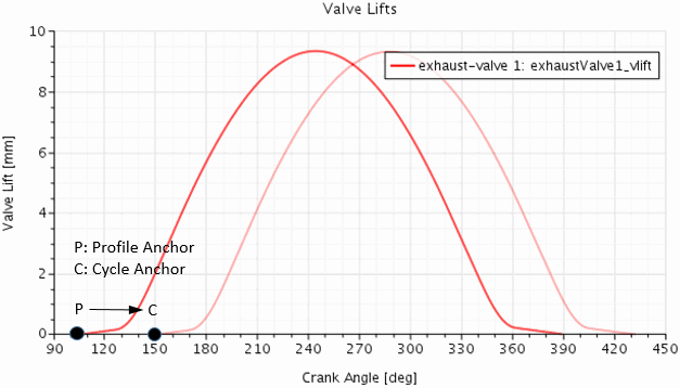 | ||
| Lift Multiplier | Modifies the actual lift of the valve (y-axis) Example: Setting lift multiplier to 0.5. 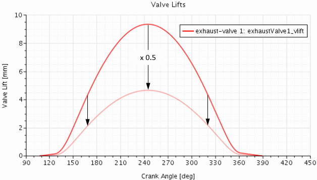 | ||
| Duration Multiplier | Modifies the duration of the valve (x-axis). Example: Setting duration multiplier to 1.2. 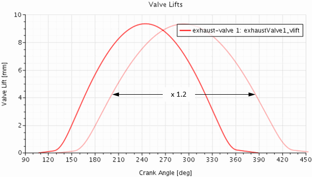 | ||
| Closure Tolerance | Specifies the valve lift that corresponds to a closed valve. Depending on the specified value and the actual valve lift, Simcenter STAR-CCM+ In-cylinder treats the valve curtain interface as follows:
| ||
| Interpolation Method | Specifies the method that is used to interpolate between the data points of the imported valve lift table. The following options are available:
| ||
| Show Table | When activated, displays the data points of the imported valve lift table in the Valve Lifts plot. | ||
| Show Lift | When activated, displays the interpolated valve lift curve with all specified modifications applied. | ||
| Show Velocity | When activated, displays the valve velocity curve. The valve velocity is derived from the valve lift curve with all specified modifications applied. | ||
| Show This Valve Only | When activated, displays only the valve lift curve for the valve that you currently edit—lift curves of other valves are hidden. | ||
| Mesh Settings | |
|---|---|
| Normalized Curtain Interface Position (not for cylinder sector model) | Specifies the location of the valve curtain as a percentage of the valve's Face radial distance. The valve curtain separates the cylinder volume from the port volumes. This property supports values between 5 and 95. When you edit the mesh settings, the Graphics window displays the valve curtain in yellow color: 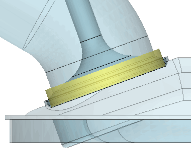 Only modify the location of the valve curtain if you encounter one of the following problems:
|
Injector Dialog
- Name
- Specifies the name of the injector under which it is stored in the tree.
| Geometry | |||||||||
|---|---|---|---|---|---|---|---|---|---|
| Injector Origin | Specifies the origin and the target of the injector axis in the chosen Coordinate System. Example: 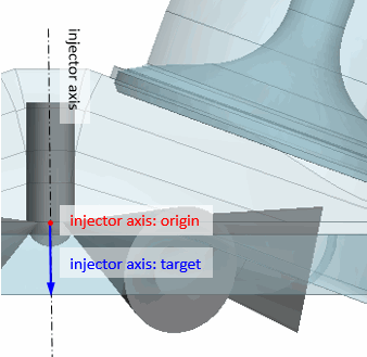 | ||||||||
| Injector Direction | |||||||||
| Number of Nozzles (not for cylinder sector models) | Specifies the number of the injector nozzles, see in Eqn. (572). For a multi-nozzle injector, the angular distance between the nozzles is given by . | ||||||||
| Nozzle Rotation Offset (not for cylinder sector models) | Specifies the angle by which to rotate the nozzle(s) around the injector axis. The direction of the injector axis gives the direction of the rotation according to the left hand rule. For a half engine model with a multi-nozzle injector, if you specify an even number of nozzles, Simcenter STAR-CCM+ In-cylinder automatically applies an rotation offset angle that depends on your engine symmetry model as tabulated below:
| ||||||||
| Per Nozzle | Depending on the injector type, the following properties are available:
| ||||||||
| Nozzle Origin Reference | Specifies the origin and the target of the nozzle axis in the chosen Coordinate Systems. Example: 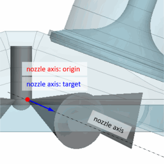 For a multi-nozzle injector, you specify the origin and the target for one of the nozzles—the reference nozzle. Simcenter STAR-CCM+ In-cylinder automatically duplicates the reference nozzle for the specified Number of Nozzles and sweeps the duplicates around the injector axis. | ||||||||
| Nozzle Target Reference | |||||||||
| Physics | |||
|---|---|---|---|
| [injector] : Injection Crank Angle Anchor | Allows you to shift the imported mass flow rate profile. For a mass flow rate profile that is a function of crank angle, the [injector] : Injection Crank Angle Anchor sets an angular position in the profile, in deg. For a mass flow rate profile that is a function of time, the [injector] : Injection Time Anchor sets a point in time in the profile, in s or in the cyclic time unit degCA. The [injector] : Injection Crank Angle Target sets the angular position in the engine cycle to which you want to shift the respective injection anchor. Example: The plot below displays a mass flow rate profile that is a function of crank angle, where the injection starts at 428 deg CA. To shift the start of injection to 450 deg CA, you set the [injector] : Injection Crank Angle Anchor to 428.0 deg and the [injector] : Injection Crank Angle Target to 450.0 deg. 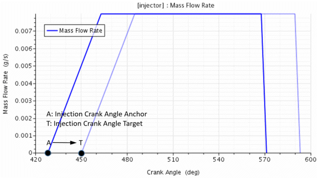
| ||
| [injector] : Injection Time Anchor | |||
| [injector] : Injection Crank Angle Target | |||
| Cone Angle Sampling Polynomial Exponent (only for solid cone and hollow cone injectors) | For nozzles of solid/hollow cone injectors, the injection in direction (in a spherical coordinate system with the injection point as the origin) is weighted so that the sample density is biased along the injection direction. where:
The Cone Angle Sampling Polynomial Exponent specifies the exponent of the polynomial function . A value of 1 results in a uniform distribution. An integer value larger than 1 results in a higher sample density at the centerline of the spray. | ||
| Mass Flow Rate | Specifies the mass flow rate of the injected fuel, see in Eqn. (572). The following options are available:
| ||
| Fuel Temperature | Specifies the initial temperature of the injected fuel. The following options are available:
| ||
| Droplet Diameter (only for hollow/solid cone injector) | Specifies the diameter of the injected fuel droplets. The following options are available:
| ||
Ignitor Dialog
- Name
- Specifies the name of the ignitor under which it is stored in the tree.
- Position
- Specifies the position of the ignitor in the chosen Coordinate System.
| Physics | |
|---|---|
| Spark Start Time | Specifies the time at which the spark is activated, in s or in the cyclic time unit degCA. See in Eqn. (3960). |
| Factor for Laminar Flame Kernel Radius (only if the the FI Spark-Ignition engine model is selected) | Specifies the factor that controls the radius of the laminar flame kernel, see in Eqn. (3958). |
| Flame Initial Distribution Parameter (only if the FI Spark-Ignition engine model is selected) | Specifies the shape parameter for the flame initial distribution function, see in Eqn. (3960). |
| Geometry / Physical Parameters (only if the ISSIM Spark-Ignition engine model is selected) | |
|---|---|
| Inter Electrodes Distance | Specifies the distance between the anode and the cathode, see in Eqn. (3969), Eqn. (3970), and Eqn. (3985). |
| Electrodes Diameter | Specifies the diameter of the electrodes. |
| Secondary Circuit Initial Energy | Specifies the initial energy of the secondary circuit of the spark plug, see for in Eqn. (3963). |
| Secondary Circuit Resistance | Specifies the resistance of the secondary circuit of the spark plug, see in Eqn. (3963). |
| Secondary Circuit Inductance | Specifies the inductance of the secondary circuit of the spark plug, see in Eqn. (3964). |
Plenum Dialog
- Name
- Specifies the name of the plenum under which it is stored in the tree.
