Mesh Strategy
Simcenter STAR-CCM+ In-cylinder generates a trimmed mesh with automatic volumetric refinements to account for various flow characteristics within the flow domain. For a cylinder sector model, Simcenter STAR-CCM+ In-cylinder generates an axisymmetric mesh.
The trimmed cell mesher generates predominantly hexahedral cells. To improve the accuracy of the flow solution near the walls, Simcenter STAR-CCM+ In-cylinder generates orthogonal prismatic cells next to wall surfaces.
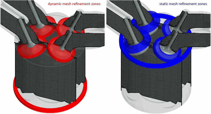
Simcenter STAR-CCM+ In-cylinder uses volume shapes to increase the mesh density in specific zones. There are two types of mesh refinement zones:
- Dynamic zones follow the moving valves and the piston to ensure a good mesh quality around the valves and the piston crevice for all crank angle positions.
- Static zones are fixed for all crank angle positions and include the cylinder seat area and the cylinder chamfer.
As the valves have an high impact on the in-cylinder flow, an accurate representation of these areas is important. Fine meshing is applied to avoid poor fluid cell quality at the valve opening and closing times. For the piston crevice and the cylinder chamfer, a fine mesh is applied to accurately capture the geometry and to avoid poor fluid cell quality at the time the piston approaches TDC.
The following images display the dynamic and static mesh refinement zones, respectively:
Additionally, Simcenter STAR-CCM+ In-cylinder uses temporary mesh refinement zones that encapsulate the valve curtain interfaces. By default, these refinement zones are only active when the valve lift of the respective valve is less than 5 times the closure tolerance.
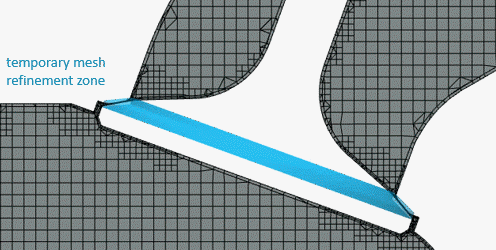
Within these zones, Simcenter STAR-CCM+ In-cylinder refines the surface mesh and reduces the thickness of the prism layers near the walls.
The default mesh settings are based on best practices to ensure a high level of accuracy in the solution with a minimum cell count. However, Simcenter STAR-CCM+ In-cylinder allows you to control specific mesh characteristics, such as the cell size in the cylinder core. The following images display the mesh for a gasoline engine using a core cylinder mesh size of 1 mm (default) and 2 mm, respectively:
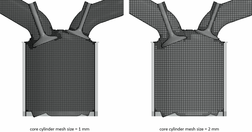
The mesh size in the refinement zones depends on the core cylinder mesh size. By default, it is half the core cylinder mesh size.
In the simulation of IC engines, the motion of the piston and valves leads to a deformation of the computational grid. Simcenter STAR-CCM+ In-cylinder models this grid deformation using the Morpher method, which redistributes the mesh vertices in response to the movement of the piston and valves. Prism layer cells next to wall surfaces are prevented from being morphed. However, when the distance between two approaching walls shrinks below the value of 3.25 times the prism layer thickness, the prism layer cells are morphed in order to maintain good mesh quality.
As cumulative deformation of the mesh decreases the quality of results, Simcenter STAR-CCM+ In-cylinder re-meshes the engine geometry based on specific criteria. For example, Simcenter STAR-CCM+ In-cylinder re-meshes the engine when the cell quality drops below a predefined value. Additionally, Simcenter STAR-CCM+ In-cylinder automatically remeshes the engine in case of negative-volume cells that can occur during the morphing process. The mesh of plenums is not deformed and therefore requires no re-meshing.
The mesh refinement zones dynamically follow the moving valves to ensure a good mesh quality around the valves for all crank angle positions.
The following animation displays the mesh deformation and re-meshing procedure:

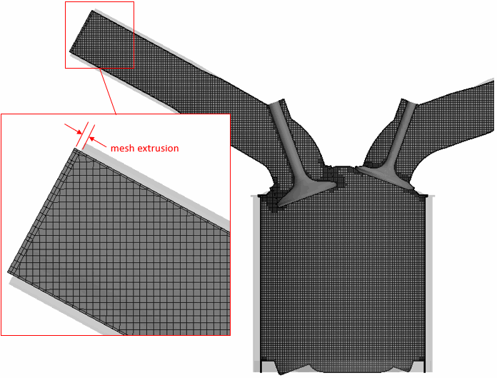
At planar inlet and outlet boundaries, Simcenter STAR-CCM+ In-cylinder allows you to extend the volume mesh with orthogonal extruded cells. This mesh extrusion is particularly useful for curved or short ports, which are not long enough for the flow to develop fully. Extruding the mesh increases the length for the flow to develop while maintaining a low cell count. Additionally, an extruded mesh allows you to prevent reversed flow and aid solution convergence.
Axisymmetric Sector Mesh
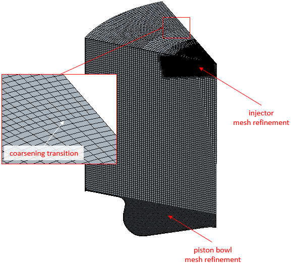
For a cylinder sector model, Simcenter STAR-CCM+ In-cylinder uses directed meshing to generate a high quality swept mesh. The method operates by sweeping a trimmed mesh from one periodic surface of the sector model to the other.
Simcenter STAR-CCM+ In-cylinder applies three rotational sweep coarsening transitions across which multiple cells are merged into a single cell. This method coarsens the mesh as it approaches the axis of symmetry.
A dynamic mesh refinement zone follows the moving piston to ensure a good mesh quality around the piston bowl for all crank angle positions. In case of fuel injection, an additional static mesh refinement zone increases the mesh density around the injector nozzle and its spray cone.
The following image displays the swept mesh for a diesel sector model with fuel injection:
Mesh Reuse
Simcenter STAR-CCM+ In-cylinder allows you to save meshes within a cycle and reuse them at the same crank angle position in the next cycle, which avoids remeshing time. Each mesh station in the cylce is saved as a Simcenter STAR-CCM+ CCM file in a specified output directory, where the name of the file includes the crank angle position as mesh identifier. Before executing a remesh, the remeshing model searches for a matching identifier within the saved meshes. If a matching identifier is found, the saved mesh file is loaded and the remesh is skipped. This approach is particularly useful for multi-cycle simulations. You can also use saved mesh files in variants of the original simulation as long as the meshing parameters are the same.