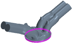
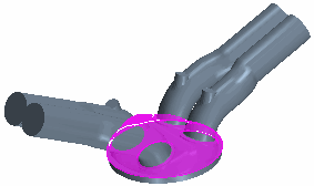
Four-Stroke Engine: CAD Bodies and Faces
For the setup of a four-stroke engine, the CAD bodies and faces of the engine geometry must meet certain criteria.
CAD Bodies
For a four-stroke engine, Simcenter STAR-CCM+ In-cylinder requires the following CAD bodies:
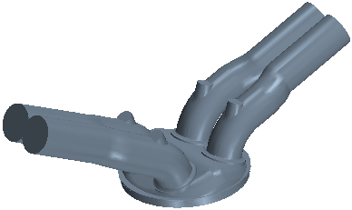
- One CAD body for the wetted surface of a single cylinder.
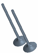
- One CAD body for each solid valve. Simcenter STAR-CCM+ In-cylinder allows a maximum of three intake valves and four exhaust valves.
- One CAD body for the wetted surface of each additional plenum that is attached to the engine (optional).
The following alignment and orientation of the cylinder and valve geometries are required:
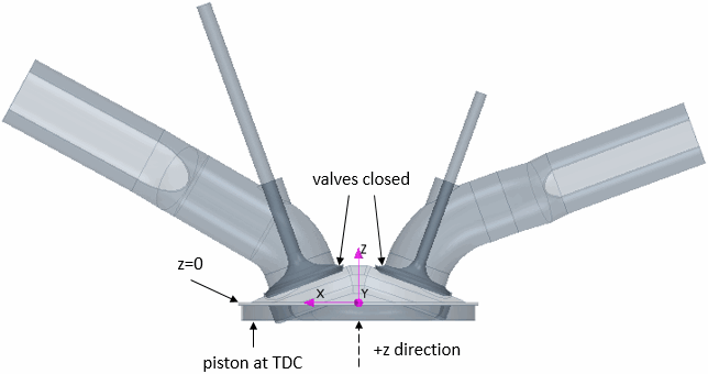
- The cylinder must be positioned so that the piston motion is along the z-axis, with the compression stroke moving the piston in the positive z-direction.
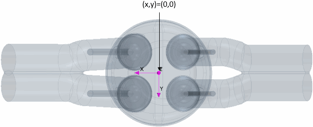
- The x and y coordinates of the cylinder centre must be at x=0, y=0.
- The firedeck z coordinate must be at z=0.
- The piston must be at the TDC position.
- All valves must be at their closed position.
To enable Simcenter STAR-CCM+ In-cylinder to recognize the engine bodies, you must name the bodies prior to CAD import in a certain manner. Simcenter STAR-CCM+ In-cylinder uses name-based Object Filters that assign the bodies to the respective Engine Parts, automatically. The following table displays the filters and the associated Engine Parts for the CAD bodies that you import:
| CAD Body |
 |
 |
 |
| Filter: CAD Body Name Contains |
|
intake AND valve AND a number (1, 2, or 3) |
exhaust AND valve AND a number (1, 2, 3, or 4) |
| CAD Body Name Examples |
|
|
|
| Engine Part |
|
|
|
CAD Faces
For the cylinder wetted surface and the valves, you must name certain faces prior to CAD import. Simcenter STAR-CCM+ In-cylinder uses the face names to assign the faces to the respective Engine Part Surfaces. The default Simcenter STAR-CCM+ In-cylinder filters work as follows:
- Cylinder
-
CAD Face 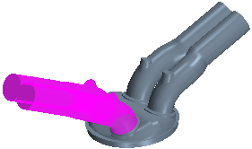
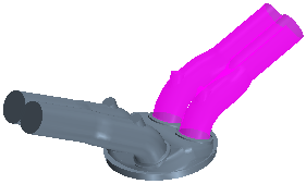
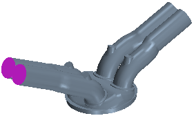
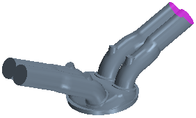
Filter: CAD Face Name Contains intake AND
port
AND NOT
inlet
exhaust AND
port
AND NOT
outlet
- inlet
- outlet
CAD Face Name Example - intake-port
- exhaust-port
- intake-port inlet
- exhaust-port outlet
Cylinder Part Surface - Intake Port
- Exhaust Port
- Inlet
- Outlet
- Intake Valve [n]
-
CAD Face 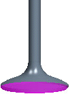
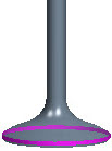
(for valves with a margin)


Filter: CAD Face Name Contains intake
AND
valve
AND
head
AND
a number (1, 2, or 3)
intake AND
valve
AND NOT
head
AND NOT
face
AND
a number (1, 2, or 3)
intake
AND
valve
AND
face
AND
a number (1, 2, or 3)
intake
AND
valve
AND
stem
AND
a number (1, 2, or 3)
- unnamed
CAD Face Name Example - intake-valve 1 head
- intake-valve 1 margin
- intake-valve 1 face
- intake-valve 1 stem
- -
Intake Valve Part Surface - Head
- [CAD face name]
- Face
- Stem
- Default : Solids
- Exhaust Valve [n]
-
CAD Face 

(for valves with a margin)


Filter: CAD Face Name Contains exhaust
AND
valve
AND
head
AND
a number (1, 2, 3, or 4)
exhaust
AND
valve
AND NOT
head
AND NOT
face
AND
a number (1, 2, 3, or 4)
exhaust
AND
valve
AND
face
AND
a number (1, 2, 3, or 4)
exhaust
AND
valve
AND
stem
AND
a number (1, 2, 3, or 4)
- unnamed
CAD Face Name Example - exhaust-valve 1 head
- exhaust-valve 1 margin
- exhaust-valve 1 face
- exhaust-valve 1 stem
- -
Exhaust Valve Part Surface - Head
- [CAD face name]
- Face
- Stem
- Default : Solids
