Solution Analysis
Simcenter STAR-CCM+ In-cylinder allows you to analyse the solution of an ICE simulation while the simulation is running as well as when the simulation completes.
To view the progress of the simulation, you generally create and open post-processing objects before running the simulation.
Simcenter STAR-CCM+ In-cylinder provides the following categories of post-processing object:
For all categories, several predefined objects are available that display specific quantities. The availability of these objects varies with the selected engine models, specified materials, and created engine parts.
| 注 | In the context of plots and reports, the term "cylinder" refers to the volume of the cylinder without the ports. This volume is limited by the valve curtain interfaces. |
Plots
Simcenter STAR-CCM+ In-cylinder provides three kinds of two-dimensional plots:
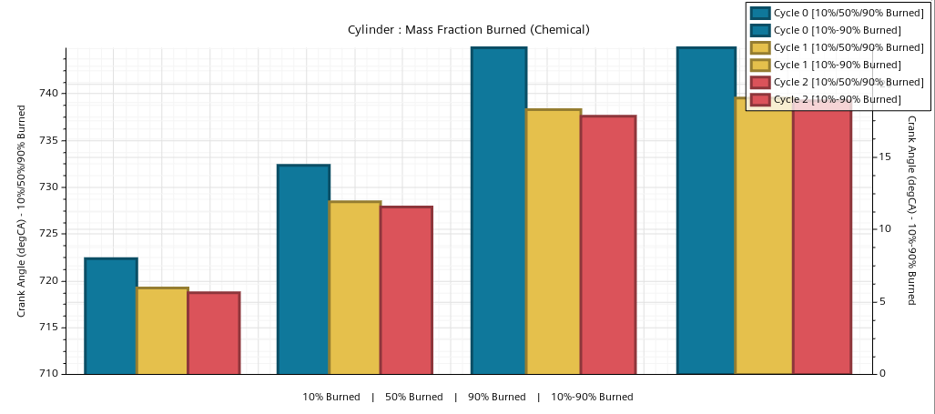
- Monitor plots—display specific values collected by monitors as functions of deg crank angle.
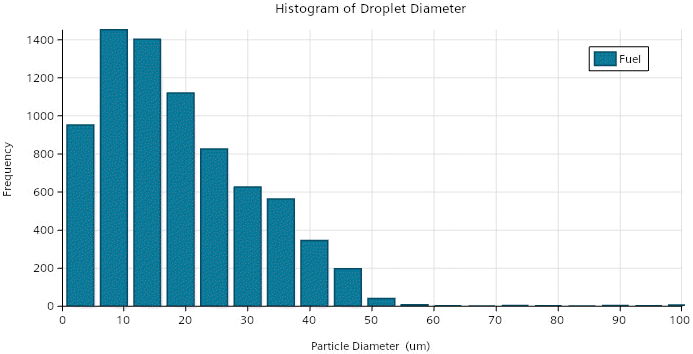
- Histogram plots—displays data distributions using bar charts.
- XY plots—displays graphs of solution data from the simulation.
For more information, see Plots.
- Monitor Plots
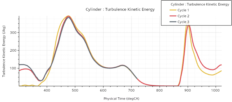
- Monitor plots display the monitored values in a cycle-by-cycle manner. Results from consecutive cycles overlap on the same plot which means you can look for cyclic convergence, or the tendency to approach a repetitive result.
- Histogram Plots
- The following histogram plot is available:
- XY Plots
- The following XY plots are available:
Reports
A report represents a computed summary of the current simulation or CPU data. Running a report returns a single value. For more information, see Reporting Results.
For each monitor plot, Simcenter STAR-CCM+ In-cylinder provides a report that returns the respective value. Additionally, the following reports are available:
- In-Cylinder - CHT Export
- CHTExport : Last Mapping Angle —returns the crank angle at which the last data mapping from the engine walls onto the shell regions was performed.
- CHTExport : Mapping Angle—returns the crank angle at which the next data mapping is performed.
- CHTExport : Mapping Delta Angle—returns the mapping interval at which the data are mapped.
- CHTExport : Start Angle Actual—returns the crank angle at which the first data mapping was performed.
- In-Cylinder - Cylinder
- Cylinder : Compression Ratio—returns the ratio of the volume of the cylinder and plenums at BTD to the respective volume at TDC using Eqn. (586).
- Cylinder : Displacement—returns the volume that is displaced when the piston moves from TDC to BDC using Eqn. (585).
- Cylinder : Fuel Molecular Weight Averaged—returns the mass average of the molecular weight of fuel in the cylinder and plenums.
- Cylinder : Peak Cylinder Pressure—returns the maximum value of the volume average of the absolute pressure inside the cylinder and plenums during the simulation.
- Cylinder : Piston Stretch Ratio—returns the ratio of the current piston z-position to the piston z-position after the last re-mesh.
- Cylinder : Piston Z—returns the piston z-position using Eqn. (569).
- Cylinder : Stoichiometric A/F Ratio Averaged—returns the stoichiometric A/F Ratio , see Materials Dialog.
- Cylinder : Trapped Mass—returns the trapped mass in the cylinder and plenums at intake valve closing (IVC). For a motored-test simulation, this value is calculated as the volume average of the density inside the cylinder and plenums. For a charge-motion simulations, the value is calculated as the volume average of the product of density and void fraction inside the cylinder and plenums. The void fraction is the fraction of the cell volume available to the fluid, unoccupied by a solid or dispersed phase.
- In-Cylinder - Emissions
- Cylinder : CO Mass Fraction—returns the mass average of the mass fraction of CO in the cylinder.
- Cylinder : CO Mole Fraction—returns the mass average of the mole fraction of CO in the cylinder.
- Cylinder : NOx Mass Fraction—returns the mass average of the mass fraction of NOx in the cylinder.
- Cylinder : NOx Mole Fraction—returns the mass average of the mole fraction of NOx in the cylinder.
- In-Cylinder - Injection
- [injector] : Start / End of Injection—returns the crank angle at which the injection of fuel from [injector] starts / ends. The respective crank angle is calculated from the imported mass flow rate table considering the optional offset given by the specified Injection Anchor and Injection Target. For more information, see Injector Dialog.
- In-Cylinder - Intermediary
- Provides various intermediate reports that are required for the definition of other reports.
- In-Cylinder - Ports and Valves
- Exhaust / Intake Valve [n] : Actual Velocity—returns the actual velocity of exhaust / intake valve [n], calculated as the time derivative of the monitored valve lift. The specified Closure Tolerance sets a lower limit to the valve lift.
- Exhaust / Intake Valve [n] : Curtain Interface Face Intersection Tolerance—returns the intersection tolerance that is used at the valve curtain interface of exhaust / intake valve [n]. The intersection tolerance limits the distance by which vertices on one side of the interface can move to match vertices, edges, and faces on the other side of the interface.
- Exhaust / Intake Valve [n] : Displacement—returns the z-position of the exhaust / intake valve [n] minus its Closure Tolerance.
- Exhaust / Intake Valve [n] : Lift Closure Check—returns
0when exhaust / intake valve [n] is closed, that is, when the z-position of the valve is smaller or equal to its closure tolerance, and1otherwise. - Exhaust / Intake Valve [n] : Stretch Ratio—returns the ratio of the current lift of exhaust / intake valve [n] to the valve lift after the last re-mesh.
- Exhaust / Intake Valve [n] : Z—returns the z-position of exhaust / intake valve [n].
- In-Cylinder - Remesh Metrics
- In-Cylinder Bad Face Validity Remesh Report—returns the number of cells that satisfy the Valid Face Criteria.
- In-Cylinder Bad Morphed Cell Remesh Report—returns the number of cells that satisfy the Bad Morphed Cell Criteria.
- In-Cylinder Morph Remesh Report—returns
1if any of the Re-mesh Criteria is satisfied and0otherwise. - In-Cylinder Skewness Remesh Report—returns the number of cells that satisfy the Cell Skewness Criteria.
- Min Cell Quality—returns the minimum cell quality of the volume mesh.
- In-Cylinder - Solution
- Crank Angle—returns the cumulative crank angle in deg.
- Crank Angle : degCA—returns the cumulative crank angle in cyclic time units (degCA).
- Crank Angle Cycle—returns the cycle wrapped crank angle (repeats 0 to cycle length) in deg.
- Crank Angle Cycle : degCA—returns the cycle wrapped crank angle (repeats 0 to cycle length) in cyclic time units.
- Cycle Length—returns the length of a cycle in deg, such as
720 degfor a four-stroke engine. - Cycle Length : degCA—returns the length of a cycle in cyclic time units, such as
720 degCAfor a four-stroke engine. - Cycle Number—returns the number of the current cycle.
- Revolutions per Cycle—returns the revolutions per cycle, such as
2for a four-stroke engine.
Scenes
Scenes allow you to visualize the geometry, mesh, and solution data that are contained in the simulation.
Scenes encapsulate the complete representation of components that are required to generate an image or an animation. Within a scene, displayers bring together parts and other attributes (such as scalars and surface properties) to produce graphics primitives which are displayed in the scene. For more information, see Visualizing the Solution.
Simcenter STAR-CCM+ In-cylinder provides a number of predefined scenes. These scenes allow you to examine specific solution fields from which you can draw conclusions about the performance of your engine.
The following predefined scenes are available:
- Absolute Pressure
- CHT Export
- Fluid Film Thickness
- Fuel Distribution
- Temperature
- Turbulent Kinetic Energy
- Velocity Magnitude
The Fuel Distribution scene allows you to visualize multiple definitions of air-fuel mixture ratio. For each definition, the scene provides a specific displayer, where the visibility of each displayer can be toggled as required.
The following definitions are available:
- air/fuel ratio—the ratio between the mass fraction of air and the mass fraction of fuel vapor. For mass fractions of fuel vapor 1.0E-10,Simcenter STAR-CCM+ In-cylinder limits the air/fuel ratio to a value of 1000.
- air/fuel equivalence ratio—the ratio between the air/fuel ratio and the stoichiometric A/F Ratio , see Materials Dialog.
- fuel/air ratio—the ratio between the mass fraction of fuel vapor and the mass fraction of air. For mass factions of air 1.0E-10, the fuel/air ratio is limited to a value of 1.
- fuel/air equivalence ratio—the ratio between the fuel/air ratio and the stoichiometric fuel/air ratio, calculated as the product of the fuel/air ratio and .
For charge-motion and combustion simulations, all predefined scenes additionally display the injected fuel parcels within the engine. On the parcels, Simcenter STAR-CCM+ In-cylinder visualizes the particle diameter by default. The screen display size of the parcels is scaled according to the particle diameter, where the particle diameter range is mapped to a physical size range of [1.0E-4 m; 4.0E-4 m] relative to the mesh dimensions. For more information, see Point Size Scale Field.
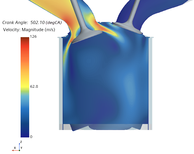
The Fluid Film Thickness scene displays the thickness of the fluid film on the engine walls. The CHT Export scene shows the cycle-averaged local heat transfer reference temperature on the engine walls. All other scenes display its respective solution field on a plane section that cuts through one of the intake valves and one of the exhaust valves and is oriented normal to the Y-direction. For example, the following image displays the Velocity Magnitude scene for a motored-test simulation:
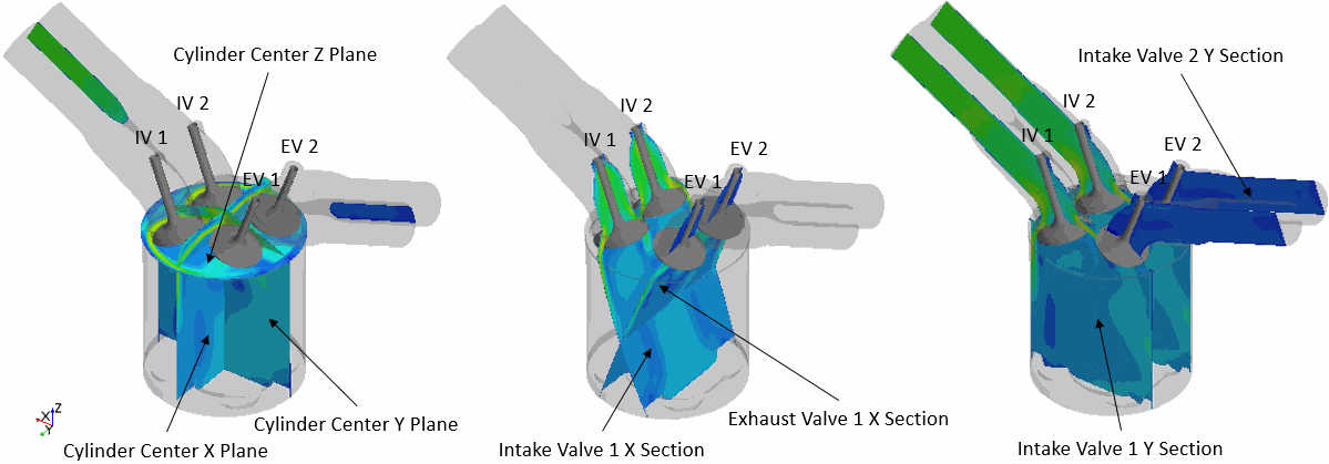
To access solution data in other areas of the engine domain, Simcenter STAR-CCM+ In-cylinder provides the following additional plane sections:
- Cylinder Center X Plane
- Cylinder Center Y Plane
- Cylinder Center Z Plane
- Exhaust Valve 1 X Section
- Intake Valve 1 X Section
- Intake Valve 1 Y Section
- Intake Valve 2 Y Section
The following image shows the location and orientation of the different plane sections for an engine with two intake valves and exhaust valves, respectively:
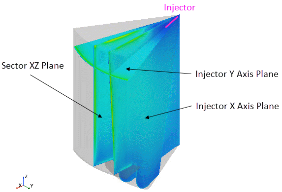
For cylinder sector models, Simcenter STAR-CCM+ In-cylinder provides the following plane sections:
- Injector X Axis Plane
- Injector Y Axis Plane
- Sector XZ Plane
The location and orientation of the Injector X Axis Plane and the Injector Y Axis Plane depend on the injector position, origin, and target. The following image shows the the different plane sections for a cylinder sector model:
Additionally, Simcenter STAR-CCM+ In-cylinder allows you to display scalar fields on cylinder and valve surfaces.
For all predefined scenes in Simcenter STAR-CCM+ In-cylinder, you can toggle the visibility of displayers and their parts as required. Removing parts from displayers is not supported—when you reload a simulation, Simcenter STAR-CCM+ In-cylinder automatically restores the removed parts.
