Prism Layer Mesher
In an Automated Mesh operation, you can use the Prism Layer Mesher in combination with a core volume mesher to generate orthogonal prismatic cell layers at wall surfaces. This layer of cells is necessary to improve the accuracy of the flow solution at wall boundaries.
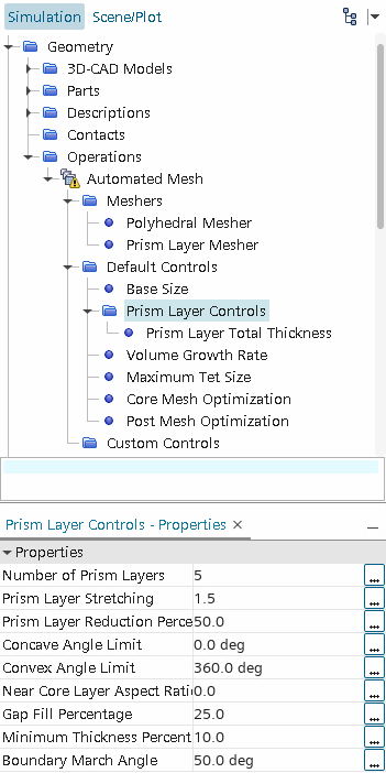
To define the prism layers, you specify:
- the total thickness
- the number of cell layers within the specified total thickness
- the size distribution of the layers
- The function that is used to generate the size distribution—either by geometric progression or hyperbolic tangent.
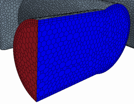
You can define these general settings globally (for all parts and part surfaces assigned to the Automated Mesh operation), and locally (for parts and part surfaces assigned to Volumetric Controls or Surface Controls, respectively). An example volume mesh showing two prism layers at the wall surface is shown below:

The minimum condition for attempting a volume mesh with prism layers is that the input surface mesh is closed, manifold, and non self-intersecting. However, meeting this condition does not guarantee a high-quality volume mesh.
- When using the Polyhedral Mesher + Prism Layer Mesher, use an isotropic input surface mesh. Anisotropic input meshes are not supported.
- When using the Tetrahedral Mesher + Prism Layer Mesher, deactivate Generate Standard Prismatic Cells.
For operations that use the Polyhedral Mesher + Prism Layer Mesher and have a Quad Dominant input surface mesh, you have the option to activate Quad Input Surface Conformality (see Quad Input Surface Conformality).
When you use a quad dominant surface mesh with prism layers, you are recommended to activate Perform Proximity Refinement. To ensure you do not limit the local proximity refinement, you are recommended to use a Minimum Surface Size smaller than the proximity refinement size. To generate a coarser mesh use a triangular surface mesh.
By default, prism layers are not created next to part surfaces unless they are assigned to wall boundaries. You can control this setting on a surface-by-surface basis, using Surface Controls.
Prism cells are not created on boundary surfaces when there is more than one boundary in a thin portion of geometry. Instead, prism layers are created inside the volume which avoids confusion between prism layers that belong to different boundaries. See Troubleshooting the Thin Meshers: Multiple Boundaries in a Thin Geometry.
By default, Simcenter STAR-CCM+ aims to generate a conformal prism layer mesh at interfaces of type in-place, periodic, or baffle, regardless of the number of prism layers at each side of the interface.
| 注 | When generating prism layers on a baffle, it is important to know that the prisms appear on the opposite sides of the baffle surface, as defined by the baffle orientation point. Consequently, for the original surface, the prisms appear on the proxy surface side, while for the proxy surface, the prisms appear on the original surface side. If you want to disable prism layers on a particular side of the baffle, this behavior is worth noting. See Baffle Contact Properties: Baffle Orientation Point Properties. |

If you remove the Prism Layer Mesher from an Automated Mesh operation, Simcenter STAR-CCM+ saves any user-defined settings and restores them if you reactivate the Prism Layer Mesher.
Why Is a Prism Layer Mesh Required?
Prism layers allow the solver to resolve near wall flow accurately, which is critical in determining not only the forces and heat transfer on walls, but also flow features such as separation. Separation in turn affects integral results such as drag or pressure drop. Accurate prediction of these flow features depends on resolving the velocity and temperature gradients normal to the wall. These gradients are much steeper in the viscous sublayer of a turbulent boundary layer than would be implied by taking gradients from a coarse mesh. Using a prism layer mesh allows you to resolve the viscous sublayer directly if the turbulence model supports it (low y+ ~1). Alternatively, for coarser meshes it allows the code to fit a wall function more accurately (high y+ > 30).
The turbulence modeling approach that is used and the desired fidelity of the physics determine the thickness, number of layers and distribution of the prism layer mesh. Depending on the Reynolds number, a turbulent shear layer requires in excess of 10-20 cells in the cross-stream direction for accurate resolution of the turbulence flow profiles. To resolve the viscous sublayer (that is, low y+ wall treatment), more cells are required. If only the gross flow features (such as a first-order estimate of skin friction) are required, coarser, high y+ wall-function type meshes with just a few prism layers can yield acceptable results.
Prism layers do not only provide near wall mesh density, they also allow high-aspect-ratio cells to be used, thus providing better cross-stream resolution without incurring an excessive stream-wise resolution.
Prism layers also reduce numerical diffusion near the wall. Numerical diffusion is a discretization error that smears discontinuities and steep gradients in a finite volume advection scheme. Numerical diffusion is minimized when the flow is aligned with the mesh. The use of prism layers greatly enhances accuracy as a result.
How is the Prism Layer Generated?
Before the core volume mesh is created, a subsurface is generated at the specified prism layer thickness values, in effect “shrinking” (for internal flows) or “expanding” (for external flows) the starting surface. The core mesh is built using this subsurface. The prism layer mesh is then generated by extruding the cell faces from the core mesh back to the original starting surface.
When the prism mesher is used with a periodic interface, then it attempts to produce a conformal mesh for the boundary pair where possible. The inclusion of a periodic interface overrules the boundary type that is specified for the boundary pair in this instance. Instead, the interface level prism layer option determines whether a prism mesh is produced or not.
Controlling the Construction of the Prism Layer
They can be split into two categories: the properties that control the general prism layer construction (such as the number of layers); and the properties that govern the behavior of the mesher when constructing a prism layer is difficult.
The following properties that govern general prism layer construction: