Default Controls
This section introduces the properties that control the general construction of the prism layer.
Properties that control the general construction of the prism layer can be set using the nodes within the node or contained in standalone nodes in the Default Controls.
Prism Layer Controls Properties
- Number of Prism Layers
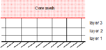
- The number of prism layers parameter controls the number of cell layers that are generated within the prism layer on a part surface or boundary. This property sets the number of prism layers to grow unless overridden by local settings or quality limits. The default value for Number of Prism Layers is to 2. Any whole value equal to or greater than 1 can be entered. The example below shows a prism mesh with three layers.
When specifying custom values, this node is added to the node.
- Prism Layer Stretching
- Prism layer stretching sets the target growth rate of successive prism layers away from the wall. The default Prism Layer Stretching value is 1.5 for the Geometric Progression method, and 0.5 for the Hyperbolic Tangent method.
- Prism Layer Reduction Percentage
- Used to calculate a threshold thickness below which the number of cell layers is progressively reduced.
- Concave Angle Limit
- Sets a limiting angle that causes the prism layer to be retracted as it approaches the apex inside a wedge. The concave and convex angle limits result in the local retraction of the subsurface where the surface edge angle is less than the concave angle limit, or greater than the convex angle limit. The purpose of which is to improve the resultant prism layer mesh quality in these areas. For example, in the case of a car wheel meeting the ground, the concave angle limit is used to retract the subsurface where the wheel and the ground meet. Doing so avoids having non-orthogonal and possibly high aspect ratio prism cells at the edge intersection of the two surfaces. The concave angle is illustrated below:
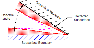
In the above diagram, the black and blue boundaries represent surfaces from which subsurfaces are generated. The dotted magenta line represents the subsurface that would have been produced without the concave angle limit being activated. With the concave angle specified to a suitable value (that is, more than the geometry interior angle), the red line represents the retracted subsurface, which results in a higher-quality prism layer mesh.
- Convex Angle Limit
- Sets a limiting angle that causes the prism layer to be retracted as it approaches the apex outside a wedge. The convex angle can be used in situations such as at the trailing edge of a wing to retract the subsurface back to give an external angle is greater than the specified limit. An example of this situation is illustrated below:
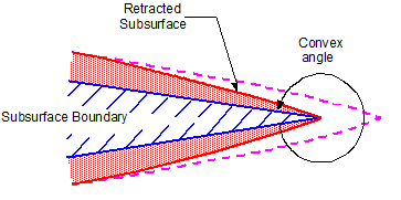
In the above diagram, the blue boundary represents the boundary surface from which a subsurface is generated. The dotted magenta line represents the subsurface that would have been produced without the convex angle limit being activated. With the convex angle specified to a suitable angle (less than the exterior angle of the geometry), the red line represents the retracted subsurface, which results in a higher-quality prism layer mesh.
- Near Core Layer Aspect Ratio
- Sets an aspect ratio between the layer thickness and cell width of the prism layer closest to the core mesh, which improves the transition from the prism layer to the core mesh.
The Near Core Layer Aspect Ratio controls the ratio between the cell height (layer thickness) and cell width of the prism cell layer closest to the core mesh. The cell faces on the core mesh (known as the subsurface) govern the prism layer cell width, and so the layer height is adjusted to set the aspect ratio. When the geometry surface is curved, the Surface Curvature control refines the mesh, which results in smaller cell widths across the curved portion. The near core layer aspect ratio becomes effective on these curved portions, as it prevents the mesher from generating long, thin cells with a high aspect ratio.
This property only affects the thickness of the cell layer that is next to the core mesh. The thickness of the remaining layers is defined according to the stretching mode and function, and with any other active constraints.
The near core layer aspect ratio is illustrated in the diagram below. The red area represents the prism layer closest to the core mesh (that is, the core mesh begins after the red line). The dashed magenta line shows the profile of the prism layer if no aspect ratio is applied.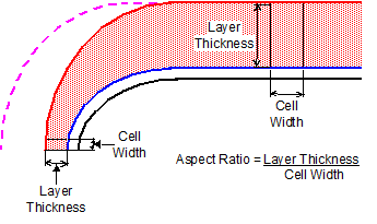
As shown above, the aspect ratio is defined as the layer thickness divided by the cell width. For example, setting a value of 2 gives a layer thickness twice as large as the cell width. To deactivate the property, set a value of 0.
The Near Core Layer Aspect Ratio is different to the Advancing Layer Mesher Limit Aspect Ratio (see Advancing Layer Mesher Reference), which stops building prism layers when the specified aspect ratio limit is reached, whereas the near core layer aspect ratio can modify the total thickness. For best results, activate the Enhanced Quality Triangle option in the surface remesher (see Surface Remesher Reference). Enhanced quality triangles provide better surface size consistency which results in smoother aspect ratio changes in the prism cells.
Using an aspect ratio improves the transition from the prism cell layers to the core mesh, as the prism layer cells are a similar size to the core mesh cells. This option also prevents “tall” cells being generated, as the aspect ratio of prism layer cells is explicitly specified. Setting the near core layer aspect ratio influences the overall prism layer thickness, particularly on curved surfaces. However, note that the overall prism layer thickness always remains at or below the user-defined value.
As an example, the following image shows a thick boundary layer without the near core layer aspect ratio specified. There are high aspect ratio cells in the prism layer due to the curvature of the geometry and associated increased surface mesh density.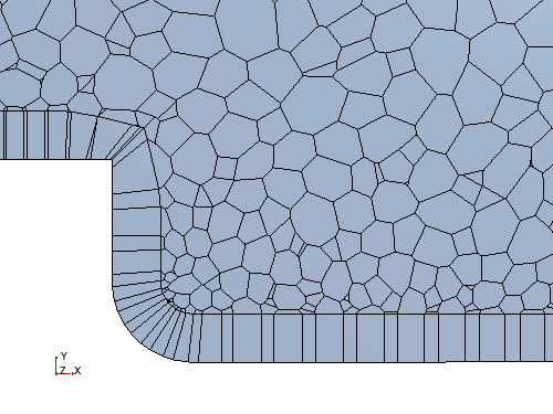 If the near core layer aspect ratio is set to 1, the transition from the prism layer to the core volume mesh is greatly improved. The volume of the prism layer cells is then closer to the volume of the adjacent core mesh cells.
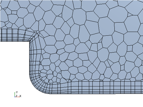
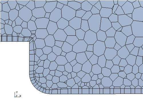 The overall prism layer thickness is reduced in this example. A more uniform thickness would be obtained by increasing the number cell layers, as shown below. You could also increase the specified aspect ratio.
- Gap Fill Percentage
- When prism layers are generated in a narrow passage (or gap), it is possible that the prism layer could become larger than the gap. The gap fill percentage sets the maximum allowable proportion of a gap that the prism layer mesh can fill.
- Minimum Thickness Percentage
- The minimum thickness percentage is used to calculate a threshold thickness below which the prism layer is retracted.
- 边界前进角
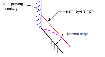
- 当棱柱层的一侧位于自身无棱柱层的边界上时,可使用边界前进角来控制其行为。
Standalone Prism Layer Controls
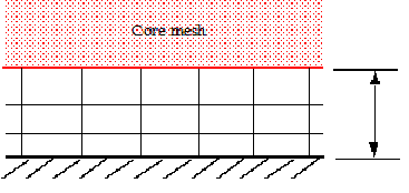
- The prism layer thickness controls the total overall thickness of all the prism layers. The Prism Layer Total Thickness size can be set using an absolute value (Absolute) or as a proportion to the base size (Relative to Base). The example below shows how the prism layer thickness is measured.
- Maximum Core/ Prism Transition Ratio
- When using the prism layer mesher with the trimmed cell mesher, you can control the ratio between the trimmed and prism layer cell sizes.
This feature, along with the Near Core Layer Aspect Ratio option, is designed to help you generate smoother cell volume transitions between the trimmed and prism layer meshes. It is set by activating the Limit Cell Size by Prism Layer Thickness property.
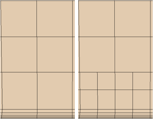
- Only available when the Limit Cell Size by Prism Layer Thickness property is activated. The Maximum Size/Thickness Ratio allows you to set a limiting value for the ratio between the two type of mesh cells. The default value is 5.0, that is, trimmed cells are refined so that they are at most five times the size of the neighboring prism layer cells. The minimum ratio value that you can enter is 2.0. Smaller values result in increased cell count. The effect of using the Size/Thickness Ratio option is shown below. The left image is with this feature turned off, and the right shows that the additional refinement has reduced the volume change between the trimmed and prism layer cells.
- Generate Standard Prismatic Cells
- This option is only available when the Tetrahedral Mesher is activated. It can be used to produce a volume mesh containing only pure tetrahedral and prismatic cells with triangular end faces. You can generate standard prismatic cells with a triangular surface mesh only.
In order to produce a volume mesh containing pure tetrahedral and prismatic cells only, the generate standard cells option can be used with the tetrahedral meshing model only. This ensures the number of prism layers used in the mesh is uniform throughout. That is, no custom number of prism layers have been set for part surfaces, regions, or boundaries. If these conditions are met, then the volume mesh that is produced can be exported to third-party packages that can only accept standard cell shapes. The default state for this option is off.
