Surface Remesher Reference
You can control the remeshing process using the properties and right-click actions for the Surface Remesher node. The properties include the meshing method and refinement options.
The properties are found under .
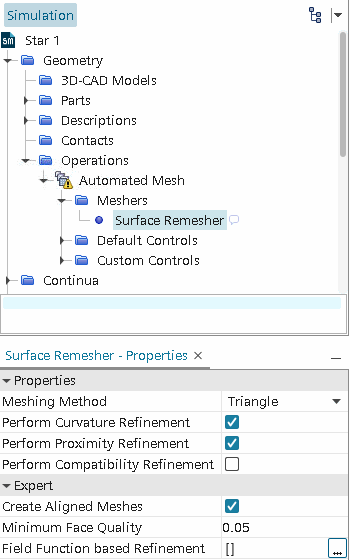
The surface curvature and surface proximity properties are common to several meshers, and as such are documented with the common surface mesher controls and values. See Surface Mesher Controls and Values.
Before you execute a volume mesh operation that uses an input surface mesh, repair any intersections in the surface mesh by activating Automatic Surface Repair (see Automatic Surface Repair).
- Meshing Method
- Specifies the shape of
the faces on the surface:
- Triangle: Creates the surface mesh using triangles.
- Enhanced Quality
Triangle: Generates triangle surfaces of higher
quality. When activated, it provides the following advantages:
- Alignment with curvature and boundaries
(feature edges, part boundaries). Enhanced quality
triangles are better at capturing the geometry and are
closer overall to the input geometry.
注 Alignment is only feasible when sizes aren't changing on a surface. In cases where they change, the alignment must be sacrificed to allow for the change in mesh size. - Allows you to better capture target sizes coming from inputs such as curvature size, surface proximity and base sizes.
However, the improved quality of the triangles increases the CPU time in generating the mesh. You are advised to only use this option as a local control for surfaces where quality and alignment are most needed.
- Alignment with curvature and boundaries
(feature edges, part boundaries). Enhanced quality
triangles are better at capturing the geometry and are
closer overall to the input geometry.
- Quad Dominant: Creates the surface mesh using quadrilaterals with the same characteristics listed above for the Enhanced Quality Triangle mesher. If you use either a Tetrahedral or Polyhedral mesher with the Advancing Layer Mesher, you can use both isotropic and anisotropic quadrilaterals. However, if you use either a Tetrahedral or Polyhedral mesher with the Prism Layer Mesher, only isotropic quadrilaterals are available. Do not use the quad dominant method on coarsely resolved geometry.
- Perform Proximity Refinement
- Activating this option allows you to refine the mesh in certain localities, especially on surfaces that are close to one another. You can specify the direction for surface proximity refinement in the Surface Proximity node. See Surface Proximity.
- Perform Compatibility Refinement
- Activating this option ensures the growth
rate in the surface is no greater than 2. This limits the difference in
face sizes across the gap between two opposing surfaces. If the gap
between the surfaces is small, the size of the faces on either side of
the gap is similar. This option is useful when using the thin mesher,
and improves volume mesh quality, as face sizes on opposing sides are
similar without explicitly stating a size.
This option is similar to proximity refinement. Proximity refinement specifies a mesh size that is based on the gap size and the number of points inside the gap. Whereas, compatibility refinement ensures that the mesh size on either side of the gap is similar. In some cases, this results in fewer elements and a more efficient use of the surface remesher.
For example, consider the surface mesh below. The curvature of the cylindrical pin reduces the mesh size near the pin: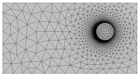 Applying compatibility refinement has the following effect on the surface mesh opposite the cylindrical pin due to the presence of square hole on the base of the thin flat plate:
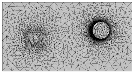
As can be seen above, the surface mesh in the region opposite to the cylindrical pin is refined, as the compatibility refinement makes the mesh size across the gap similar to the mesh of the hole. Note that the surface growth rate also influences the mesh size, so the sizes are not identical. The refinement on the surface mesh in turn affects the volume mesh by creating refined and better quality cells in the gap between the pin and opposing surface.
- Create Aligned Meshes
- Activating Create Aligned Meshes generates a surface mesh
with face edges that aim to follow the curvature of rounded CAD
features, such as fillets. The following issues can prevent the surface
remesher from generating an aligned mesh:
- An aligned mesh reduces the overall surface mesh quality.
- The aligned meshing conditions are not met.
- The underlying geometry is not suitable for aligned meshing.
The Create aligned mesh option is a property of the Surface Remesher meshing model, and is activated by default. Use the checkbox to deactivate aligned meshing. The following example illustrates the effect of the Create aligned mesh option. The blue sections highlight CAD edges for comparison between this surface mesh and those in the previous section.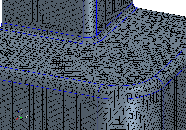
Currently, the following conditions apply to the Create Aligned Meshes option:
-
Aligned sections must have 4 sides and have geometric features as closed boundaries, for example:
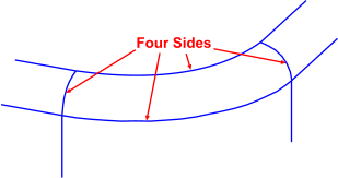
- There must be less than a 30% difference between the number of vertices that the surface remesher creates on opposing sides of an aligned section.
- The remeshed surface must have a relatively uniform surface mesh size. As a general guideline, the minimum surface size (without aligned meshing) must be greater than half of the maximum surface size.
- Aligned meshes cannot lie on a periodic interface boundary, or be connected to one along an edge (in-place interfaces are supported).
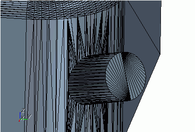
- Aligned
sections cannot contain inner loops, such as an inlet duct on a
filleted edge:
- Minimum Face Quality
- Simcenter STAR-CCM+ attempts to
generate a surface mesh with a face quality equal to or greater than the
specified Minimum Face Quality.
The quality of a triangular face is defined as:
where is the radius of the circle that passes through the three corner points of the triangle and is the radius of the circle inscribed in the triangle. A value of 0 represents a degenerate, zero area face and 1 represents a face with perfect face quality.
For the Minimum Face Quality, you can specify a value in the range [0.0, 0.2]:- Recommended values are in the range 0.01 to 0.2.
- Setting the value to 0 means that the mesher does not attempt to achieve a minimum face quality. This is not recommended when using the Quad Dominant or Enhanced Quality Triangle meshing method.
To achieve the minimum quality, Simcenter STAR-CCM+ is allowed to modify part curves to improve or remove faces whose quality is below the specified value.
- Field Function based Refinement
- Allows you to refine the mesh using field functions or a mesh size table, based on an existing solution.
Right-Click Actions
- Restore Default Settings
- Allows you to restore all properties to the default value.