Contact with a Rigid Surface
A rigid contact constraint defines a boundary condition on the surface of a deformable solid. This boundary condition accounts for the contact between the solid and a rigid surface that is not part of the stress analysis.
Currently, Simcenter STAR-CCM+ allows you to model frictionless contacts with rigid planes.
Contact Pressure
Consider the interface between a deformable solid and a rigid plane .
The traction vector on (that is, the side of the interface belonging to the deformable solid) can be decomposed into its tangential and normal components:
where is the tangential Piola traction vector and is the nominal contact pressure relative to the initial, undeformed, contact surface [870]. The contact pressure is defined to be positive in compression.
For frictionless contacts, the only contribution to the traction vector comes from the normal component, that is, the contact pressure. The contact pressure on the initial surface is related to the pressure on the current, deformed, surface through:
where is the contact pressure relative to the current surface and is the jacobian that relates the initial and current surfaces:
The contact conditions in the normal direction can be formulated as a Karush-Kuhn-Tucker condition [870]. For each point on the contact surface :
where is the contact gap function that defines the distance between a point on the solid body surface and its projection on the rigid obstacle surface.
Contribution of the Contact Pressure to the Virtual Work
For frictionless contacts, only the contact pressure contributes to the virtual work equation for the deformable solid (Eqn. (4464)), which becomes:
where the last term on the left-hand side is the contact contribution. The variation of the contact gap is given by:
where is the surface normal pointing out of the rigid surface.
Penalty Method for Contact Enforcement
Simcenter STAR-CCM+ models the relationship between the contact pressure and the gap function using the penalty method. The penalty method models the hard contact by penalizing any nonphysical penetrations of the solid body into the rigid surface.
With this approach, the relationship is defined as:
where is defined as:
and is a parameter that penalizes the nonphysical penetrations. With Eqn. (4488), the contact contribution in Eqn. (4486) can be written as:
The penalty method describes a perfectly rigid contact only for . Any finite value introduces a modeling error. However, too large values can impair the convergence of the numerical schemes. Therefore, the penalty parameter value must be chosen as a compromise between modeling accuracy and numerical stability. The optimal value of is related to the stiffness of the solid material and the mesh size:
where represents the material stiffness and is the numerical accuracy, that is, the finite element's size.
Uzawa Algorithm for Contact Enforcement
where is the current contact pressure ( ). The fixed point scheme is updated until the impenetrability condition ( ) is satisfied.
where is the normalization factor and is the reference length, currently
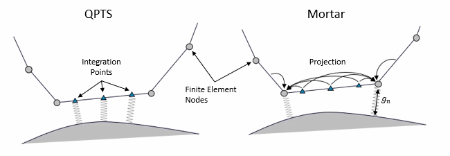
Discretization of the Rigid Contact Gap

- Quadrature Point to Surface scheme (QPTS)
- The quadrature point to surface scheme (QPTS) computes
the exact contact gap for the finite element
integration points using Gaussian integration, and
applies the penalty method directly to the contact
gap values for the integration
points:(4498)
- Mortar
- In contrast, the Mortar discretization introduces a
finite element discretization of the contact
pressure:(4499)