Conjugate Heat Transfer and Thermal Stress: Exhaust Manifold
Simcenter STAR-CCM+ allows you to combine the advantages of the finite volume (FV) and the finite element (FE) methods together in the same simulation.
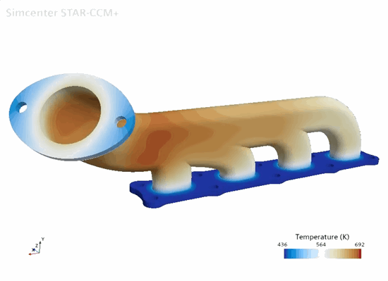
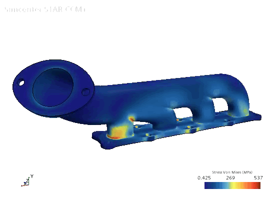
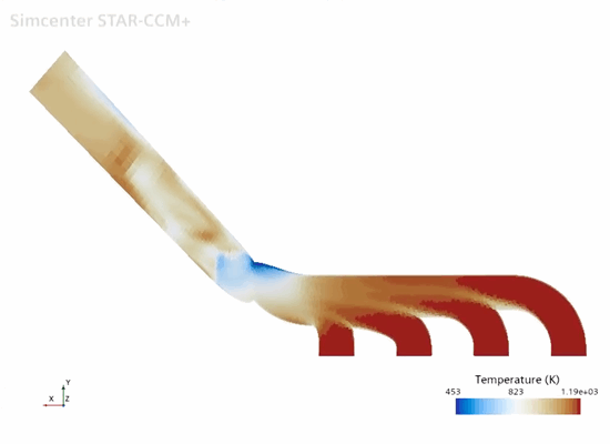
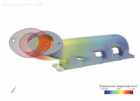
In this tutorial, you study the thermal expansion of an exhaust manifold in response to hot gas entering the inlets. The simulation incorporates both conjugate heat transfer (CHT) between the solid and the fluid, and thermal expansion in the solid due to the temperature changes. For the gas, you solve for fluid flow and energy using the FV method; for the manifold, you solve for the solid temperature and corresponding thermal stress using the FE method.
| Conjugate Heat Transfer (CHT) | Solid Thermal Expansion and Stress |
|---|---|
Solid
Temperature |
Solid
Stress |
Fluid
Temperature |
Solid
Thermal Expansion |
In the simulation, you first solve for conjugate heat transfer in order to compute the steady-state temperature distribution throughout the manifold. You then run the solid stress solver in order to compute the thermal strain on the manifold. The simulation strategy, including the model geometry and assumptions, is summarized below.
CHT Analysis
| Solid Domain | Fluid Domain | |
|---|---|---|
| Geometry | Imported CAD model | Extracted from solid geometry using part operations |
| Mesh | Tetrahedral elements with mid-side nodes | Polyhedral cells. The mesh is extruded at the outlet. |
| Assumptions and Models |
|
|
| Boundary Conditions | Outer boundaries:
Convection
Cylinder head boundary: constant temperature of 440 K |
|
| Type of Analysis | Steady | Steady |
| Discretization and Solution Method | Finite element (FE) | Finite volume (FV) |
Thermal Strain Analysis
| Solid Domain | |
|---|---|
| Geometry | Same as above |
| Mesh | Tetrahedral elements with mid-side nodes |
| Assumptions and Models |
|
| Boundary Conditions |
|
| Type of Analysis | Static |
| Discretization and Solution Method | Finite element (FE) |