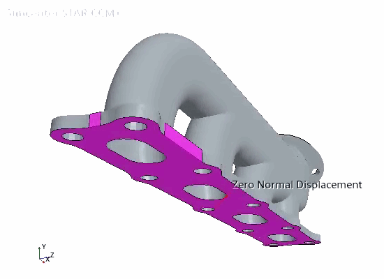
Constraining the Solid Part
When constraining a part for thermal-structural analysis, it is important to avoid constraints that are too restrictive and lead to unrealistic stress concentrations. In this simulation, you constrain three mutually orthogonal surfaces on the manifold, thus preventing displacement in the direction normal to surfaces. This set of constraints prevents rigid body motion while allowing free expansion of the solid structure.
As you apply the same type of constraint (normal displacement) on all surfaces, you require a single segment. To create the segment:
- Right-click the node and select .
- Rename the node to Zero Normal Displacement.
-
Edit the
Zero Normal Displacement node and set the following properties:
Node Property Setting Zero Normal Displacement Surfaces - ExternalXMinus
- ExternalZPlus
- ToCylinderHead
Type Constraint 
Method Normal Displacement 
Value 0.0 m (default)
To visualize the constrained surfaces:
-
Open the
Manifold Geometry scene. In the simulation tree, select the
Zero Normal Displacement segment node.

- Save the simulation.