Selecting the Physics Models and Materials
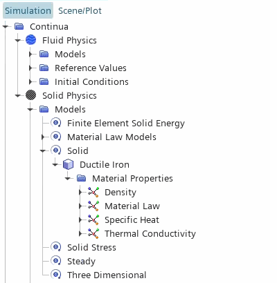
This simulation requires two physics continua—one for the gas region and one for the manifold region. In the fluid and solid regions you solve for conjugate heat transfer using the finite volume Segregated Fluid Temperature model and the Finite Element Solid Energy model, respectively. In the solid region, you also solve for thermal expansion in response to the temperature change.
To define the physics continua:
- Expand the Continua node.
- Rename the existing continuum, Physics 1, to Fluid Physics.
- Create a new physics continuum
- Rename the Physics 1 node to Solid Physics.
-
Select the
node and set
Physics Continuum to
Solid Physics.
The Fluid physics continuum is already assigned to the Fluid region.
In this simulation, you model the gas as turbulent air entering the inlets at a temperature of 1200 K. To specify the models that define the behavior of the gas:
- Right-click the node and select Select models....
-
In the Fluid Physics Models Selection dialog,
select the following models in order then click Close:
Group Box Model Space Three-Dimensional (already selected) Enabled Models Solution Interpolation (already selected) Time Steady Material Gas Flow Segregated Flow Enabled Models Gradients (selected automatically) Equation of State Ideal Gas Energy Segregated Fluid Temperature Viscous Regime Turbulent Turbulence Reynolds-Averaged Navier-Stokes (selected automatically) Reynolds-Averaged Turbulence K-Epsilon Turbulence Enabled Models Realizable K-Epsilon Two-Layer (selected automatically) Two-Layer All y+ Wall Treatment (selected automatically) Wall Distance (selected automatically) The default fluid material (air) and its properties are appropriate for this case.
Initialize the gas temperature to 1200 K:
- Select the node and set Value to 1200 K.
Specify the physics models that define the manifold behavior. To solve for the temperature throughout the manifold, you activate the
Finite Element Solid Energy. To solve for the thermal expansion in response to temperature changes, you activate the
Solid Stress model:
- Double-click the node.
-
In the Manifold Physics Models Selection
dialog, select the following models in order then click
Close:
Group Box Model Space Three Dimensional Time Steady Material Solid Optional Models Finite Element Solid Energy Optional Models Solid Stress Enabled Models Material Law Models (selected automatically)
To specify the solid material:
- Expand the node.
- Right-click Al and select Replace with...
- In the Replace Material dialog, select and click OK.
-
Expand the
node.

To model heat conduction in the manifold, you define the specific heat and thermal conductivity of the solid material. For this simulation, the default values for ductile iron are appropriate. To model thermal expansion, you define the material law that approximates the stress-strain relationship in the solid. In this simulation, you assume that:
- the stress-strain relationship is isotropic linear elastic
- the thermal expansion in response to the thermal load is isotropic
To define the material law:
- Expand the node.
- Rename the node to Isotropic Linear Elastic.
-
For the Isotropic Linear Elastic law node, select the
following models then click Close:
Group box Model Material Stiffness Models Linear Elasticity Material Strain Measures Linear Strain (Small Strain) (selected automatically) Linear Elastic Material Models Isotropic Linear Elasticity Optional Models Thermal Expansion (selected automatically) Thermal Expansion Material Models Isotropic Thermal Expansion -
Expand the node.
By default, Simcenter STAR-CCM+ sets Type to the default material Law, Isotropic Linear Elastic.
Simcenter STAR-CCM+ activates additional material properties based on the material law models that you selected. The default values are appropriate for this case.
Specify an initial value for the manifold temperature:
- Select the node and set Value to 420 K.
To improve accuracy of the finite element solution, enable mid-side vertices on the manifold mesh:
-
Select the
and set
Mid-side Vertex to
Add - Linear Interpolation.
Simcenter STAR-CCM+ generates the mid-side nodes during solution initialization.
- Save the simulation.