Extracting the Fluid Geometry
To create a geometry part for the fluid, you use operations that extract the internal fluid volume from the solid manifold geometry.
- Right-click the node and select .
-
In the
Create Fill Holes Operation dialog, set the following properties:
Property Setting Input Parts Manifold End Curves - ToCylinderHead
- ToTurbo
Execute Operation Upon Creation Activated -
Click
OK.
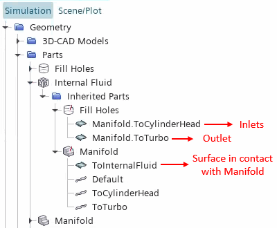
Simcenter STAR-CCM+ executes the operation and creates a part named Fill Holes. This part contains the surfaces that close the inlet and outlet.
To extract the internal fluid volume:
- Right-click the Operations node and select .
-
In the
Create Extract Volume Operation dialog, set the following properties:
Property Setting Parts - Fill Holes
- Manifold
Execute Operation Upon Creation Activated -
Click
OK.
Simcenter STAR-CCM+ creates a part named Extract Volume.
-
Select the
node and rename it
Internal Fluid.
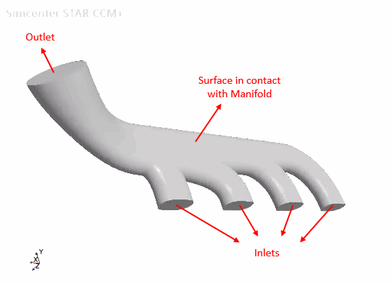
The Internal Fluid part contains the required inlet, outlet, and internal surface:

To visualize the extracted fluid volume, you can add the surfaces of the Internal Fluid part to a geometry scene.
- Save the simulation.