Creating Regions, Boundaries, and Interfaces
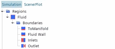
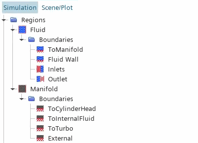
This simulation requires two regions, one for the solid manifold and one for the fluid. The two regions exchange thermal data at a fluid-solid interface. The fluid region contains an internal interface between the fluid inside the manifold and the fluid extrusion at the outlet.
In this simulation, you group multiple part surfaces under the same boundaries, based on the physics conditions that you apply. For this reason, it is convenient to create the regions and boundaries manually, rather than using the Assign Parts to Regions dialog.
To create the fluid region:
- Expand the node and multi-select Fluid Outlet Extrusion and Internal Fluid.
- Right-click one of the selected part and select Set New Region...
- Set New Region Name to Fluid and click OK.
- Expand the node.
- Rename the Default node to Fluid Wall.
- Right-click the Boundaries node and create a new boundary
- Rename the Boundary 1 node to Inlets.
-
For the
Inlets boundary, set the following properties:
Property Setting Part Surfaces Type Mass Flow Inlet -
Following the same procedure, create a new boundary and rename it to
Outlet and set the following properties:
Property Setting Part Surfaces Type Pressure Outlet
In general, it is good practice to assign the surfaces that belong to an interface to a separate boundary. This practice is useful when troubleshooting interface issues, as you can check whether the boundary faces are correctly mapped to the interface boundary. To create a boundary for the fluid surfaces that interface the solid:
- Within the Fluid region, create a new boundary.
-
Rename the Boundary 1 node to
ToManifold and set the following properties:
Property Setting Part Surfaces Type Wall 
To create the solid region:
- Right-click the node and select .
- Set New Region Name to Manifold and click OK.
- Select the node and set Type to Solid Region.
- Rename the node to External.
-
Right-click the
Boundaries node and create new boundaries with the following settings:
Boundary Name Part Surfaces ToCylinderHead ToCylinderHead ToInternalFluid ToInternalFluid ToTurbo ToTurbo 
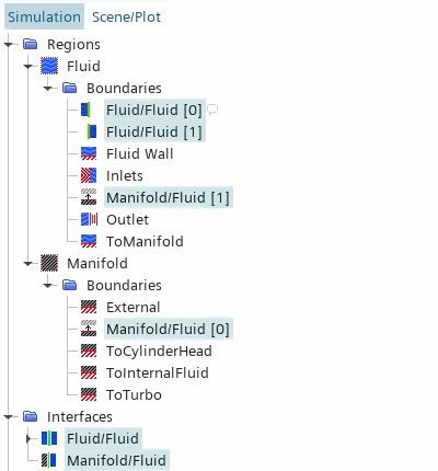
This simulation requires two interfaces—one interface in the fluid region between the internal fluid and the fluid extrusion, and one interface between the fluid and the solid regions. As the fluid and the solid domains use different discretization methods for the CHT solution (finite volume for the fluid and finite element for the solid), you require a non-conformal interface at which data is mapped between the different mesh representations.
To create the internal interface between the fluid extrusion and the internal fluid:
- Expand the node.
- Right-click the node and select Set New Interface...
To create the interface between the fluid and the manifold:
- Right-click the node and select Set New Interface...
-
Select the
node and set
Type to
Mapped Contact Interface.

- Save the simulation.