Reference Geometry Options
Adjust the reference geometry options.
Reference Point Options
Define the reference point using the following options.
| Point by Location | |
| Coordinate System Source | Specifies the coordinate system to use for the point. You can use a Reference Coordinate System, or an Imported Cartesian, cylindrical, or spherical coordinate system. |
| Location (X, Y, Z)/(R, θ, Z)/(R, θ, φ) | Specifies the coordinates for the reference point. You can either type the coordinates directly or use the widget within the 3D-CAD View window. If you set the location using a design parameter, the widget is hidden in the scene. |
| Point by Offset | |
| Offset From | Specifies an existing point from which to offset the reference point. The existing point can be that on a body or that of an existing reference point. |
| Offset | Specifies the offset distance for the reference point. Leaving the offset distance as zero creates a reference point on the existing point. |
| Point From Entity Center | |
| Entity | Specifies the point at the center of the selected edge for cylindrical or elliptical entities, or at the center of the toroidal or spherical geometry. |
| Center Type | Specifies how the center for the selected entity is calculated. Some of the options are deactivated depending on the entity that you select. Centroid uses the center of mass of the geometric object. Geometry Center uses the equidistant point from all the points that are lying on the geometric object, for example a circular edge or a spherical face. For elliptical edges, the geometry center is the intersection of its major and minor axes. For toroidal faces, the geometric center is the center of revolution. Midpoint is the midway between the two extremes of a geometric object, for example, the halfway-point along an edge, or the center of a face. |
| Point by Projection | |
| Source Point | Specifies an existing point from which to project to the target entity. The existing point can be that on a body or that of an existing reference point. |
| Target Entity | Specifies the target plane, surface, or edge to project to. The target plane or surface can be planar or non-planar. The target edge can be linear or non-linear. |
| Point by Import | |
| File Name | Specifies the file to import. The file must be in CSV (Comma Separated Value) format. The rows in the file define the points to create, while the columns define the [X, Y, Z] coordinates for the reference point. |
Reference Axis Options
Define the reference axis using the following options.
| Axis By Definition | |
| Coordinate System Source | Specifies the coordinate system to use for the axis. You can use a Reference Coordinate System, or an Imported Cartesian, cylindrical, or spherical coordinate system. |
| Origin (X, Y, Z)/(R, θ, Z)/(R, θ, φ) | Specifies the origin of the axis. You can specify the coordinates of the origin directly or use the widget in the 3D-CAD View window. If you set the origin using a design parameter, the widget is hidden in the scene. |
| Direction (X, Y, Z)/(R, θ, Z)/(R, θ, φ) | Specifies the direction of the axis. |
| Axis By Two Points | |
| Start Point | Specifies the start point and end point for the reference axis. |
| End Point | |
| Axis From Linear Entity | |
| Linear Entity | Specifies the linear edge for the axis. The reference axis is collinear with the selected edge. |
| Axis From Revolved Entity | |
| Revolved Entity | Specifies the face of the revolved entity. The reference axis is created on the axis of revolution. |
| Axis From Point and Plane | |
| Through Point | Specifies the origin of the axis. Select an existing point from the 3D-CAD View scene. |
| Normal Plane | Specifies the axis direction. Select a plane or planar surface from the 3D-CAD View scene. The direction is normal to the selected plane. |
| Axis By Intersecting Planes | |
| Planar Entity 1 | Specifies the planes and/or planar surfaces, whose intersection defines the axis. |
| Planar Entity 2 | |
| Axis From Arc | |
| Edge | Specifies a partial/full circular edge to use for the axis. The axis is created through the geometric center of the edge. 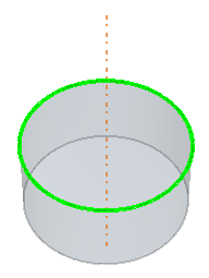 |
Reference Plane Options
Define the reference plane using the following options.
| Plane By Definition | ||
| Coordinate System Source | Specifies the coordinate system to use for the plane. You can use a Reference Coordinate System, or an Imported Cartesian, cylindrical, or spherical coordinate system. | |
| Origin (X, Y, Z)/(R, θ, Z)/(R, θ, φ) | Specifies the coordinates of the origin of the plane. You can specify the coordinates of the origin of the plane or you can use the widget within the 3D-CAD View window. If you set the origin using a design parameter, the widget is hidden in the scene. | |
| X Direction (X, Y, Z/(R, θ, Z)/(R, θ, φ)) | Specifies the direction vector for the X direction of the plane. | |
| Y Direction (X, Y, Z)/(R, θ, Z)/(R, θ, φ) | Specifies the direction vector for the Y direction of the plane. | |
| Renormalize | Makes sure that the X and Y directions of the sketch plane are normal to each other. Clicking this button can result to changes in some of the specified values. | |
| Plane By Transformation | ||
| Transform From | Specifies the plane or planar face from which the new plane is transformed. | |
| Translation Vector | Specifies the direction and magnitude of the translation for the plane or use the triad within the 3D-CAD View window. If you set the vector using a design parameter the triad is hidden in the scene. | |
| Rotation Angle | Specifies the rotation of the plane. | |
| Plane By Three Points | ||
| Origin | Specifies the origin of the plane. Select a point from the 3D-CAD View scene. | |
| Point on X-axis | Specifies the X-axis for the plane. Select a point from the 3D-CAD View scene. | |
| Point on X-Y plane | Specifies the XY plane. Select a point from the 3D-CAD View scene. | |
| Plane From Point and Axis | ||
| Point | Specifies the origin for the plane. Select an existing point from 3D-CAD View scene. | |
| Axis | Specifies the normal of the plane. Select a linear edge or reference axis from the 3D-CAD View scene. This edge must not coincide with the point chosen as the origin. The positive X-axis of the plane is the implicit projection of the specified origin onto the specified linear edge or reference axis. | |
| Placement | Specifies placement of the plane. On Point sets the plane on the selected point. On Axis sets the plane on the selected axis. | |
| From Curve | ||
| Curve Source | Edge Chain | Specifies the input curve for the plane, where the curve is defined by a simply connected chain of edges (edge chain). |
| Sketch | Specifies the input curve for the plane, where the curve is defined by a 2D or 3D Sketch that contains a single loop of sketch segments. | |
| Location | By Curve Parameter | Value from 0 to 1. The plane is positioned proportionally along the input curve parameter. |
| By Curve Length | Value from 0 to the total length of the curve source. The plane is positioned proportionally along the input curve length. | |
| Flip | When activated, flips the plane placement along the curve chain. | |
| Type | Defines the orientation of the plane. | |
| Normal Plane | The plane is created normal to the input curve. | |
| Fitting Plane | The plane is created planar to the input curve. The image below shows an example for Normal Plane and Fitting Plane. 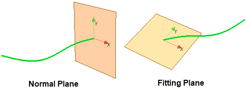 | |
| Alignment of X-Axis | Allows you to control the orientation of the plane. | |
| Automatic | Selected by default and allows you to use either curve normal/bi-normal definition (if available), or the global x and y axes for the plane. | |
| By Point | Allows the x-axis of the created plane to point towards a specified point (reference point or vertex). | |
| Plane From Surface | ||
| Face | Specifies the face to use for the plane. | |
| Type | Defines the orientation of the plane. | |
| Tangent Plane | The plane is created tangent to the input face.  | |
| Section Plane | Allows you to create a section plane perpendicular to the input face. 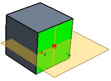 | |
| Origin Definition | Allows you to control the horizontal and vertical position of the plane. | |
| U Parameter | Precise parametric location of the U position on the input face. | |
| V Parameter | Precise parametric location of the V position on the input face. | |
| Offset Distance | Allows you to offset the tangent plane by a specified distance. | |
| Offset Angle | Allows you to offset a section plane by a specified angle. | |
| Alignment of X-Axis | Determines the orientation of the x-axis of the resulting plane. | |
| Along U Tangent | Selected by default and x-axis extends from the (U,V) origin in the direction of U. | |
| Along V Tangent | X-axis extends from the (U,V) origin in the direction of V. | |
| Flip Normal | When activated, flips the direction of the plane normal. Only the x and y axis directions are shown in the scene, hence you are advised to predict the normal direction based on the right-hand rule. | |
| Plane From Arc | ||
| Edge | Specifies a partial/full circular edge to use for the plane. The plane is created perpendicular to the input edge. 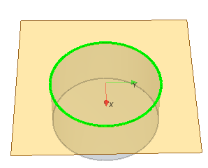 | |
Reference Coordinate System Options
Define the reference coordinate system using three points.
| Coordinate System by Definition | |
| Origin (X, Y, Z) | Specifies the origin of the coordinate system. Define the [X, Y, Z] coordinates of the origin or use the triad within the 3D-CAD View window. If you set the origin using a design parameter the triad is hidden in the scene. |
| X-Axis Direction (X, Y, Z) | Specifies the X-axis for the coordinate system. Define the direction of the X-axis using [X, Y, Z] coordinates. |
| Point on X-Y Plane (X, Y, Z) | Specifies a vector on the XY plane which is formed by a point on the XY plane and the origin. The Y-axis is a special case of this vector. Define a direction vector that lies on the XY plane using [X, Y, Z] coordinates. |
| Coordinate System By Three Points | |
| Origin | Specifies the origin of the coordinate system. Select a point from the 3D-CAD View scene. |
| Point on X-axis | Specifies the X-axis for the coordinate system. Select a point from the 3D-CAD View scene. |
| Point on X-Y plane | Specifies the XY plane of the coordinate system. Select a point from the 3D-CAD View scene. |
| Coordinate System by Import | |
| Imported Coordinate System | Imports an existing local coordinate system that you created in Simcenter STAR-CCM+. See Creating a Local Coordinate System. |
| By Transformation—allows you to transform the definition of the Source coordinate system so that it has the same relative position and orientation in the To Frame coordinate system that it had in the From Frame coordinate system. (Similar to transforming a body) | |
| Source | Specifies the source coordinate system from which you take the transformation so that a new coordinate system is created. |
| From Frame | Specifies the initial frame of reference. |
| To Frame | Specifies the target frame of reference. |
| Coordinate System From Point and Axis | |
| Point | Specifies the origin of the coordinate system. Select a point from the 3D-CAD View scene. |
| Axis | Specifies the Z-direction of the coordinate system. The positive Y-axis is defined using the right-hand rule for the cross product between the Z-axis and X-axis. Select a linear edge or axis from the 3D-CAD View scene that does not pass through the origin. |
| Placement | Specifies placement of the origin. On Point sets the origin for the coordinate system as the selected point. On Axis sets the origin on the selected axis. |
| Coordinate System From Point and Plane | |
| Point | Specifies the point that the X-axis and Y-axis pass through. Select a point from the 3D-CAD View scene. |
| Plane | Specifies the Z-axis of the coordinate system. The X and Y directions of the coordinate system are the same as the X and Y directions of the plane or planar surface. Select a plane or planar surface from the 3D-CAD View scene. The positive Z-axis is normal to the selected plane or planar surface. |
| Placement | Specifies placement of the origin. On Point sets the origin for the coordinate system as the selected point. On Plane sets the origin on the selected plane or planar surface. |
| Coordinate System From Arc | |
| Edge | Specifies a partial/full circular edge to use for the coordinate system. The coordinate system is created at the geometric center of the edge. The Z-axis of the coordinate system is parallel to the edge-plane.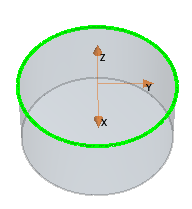 |