Setting Up a Design Study
Setting up a design study requires that you choose the type of study, set its properties, and choose appropriate input parameters and responses. Additionally, you choose scenes and plots that you want Design Manager to export from each design simulation.
Design Manager supports multiple design studies in one Design Manager project.
-
Right-click the
Design Studies node and select
New.
Simcenter STAR-CCM+ creates a [design study] node, which you can rename as desired. If you run the design study on Windows, be aware that the overall path (including the filename that comes from this node) must not exceed 260 characters.
For a new design study, a warning badge on the [design study] node indicates that the setup of the design study is incomplete.
-
Configure the design study. For any of the child nodes, you can copy and paste nodes from other studies in the project.
For detailed information on the settings that Design Manager requires for each study type, see Study Type Settings Reference.
Before selecting the input parameters that this design study requires, go through each parameter available in the node and set Simulation Effect for each one. This setting is used to optimize the design exploration process. If two or more designs have the same mesh parameters, the mesh is computed for the first design and is cached. This stored mesh is then reused for the remaining designs, rather than repeating the meshing calculation for each design. For more information, seeSetting Up Simulation Effect for Simulation Parameters.
-
To set the Simulation Effect property, expand the node (and any child nodes where present). Select each
[input parameter] in turn and set its Simulation Effect property to one of the following
options:
-
Unknown: Implies the parameter affects everything (that is, geometry, meshing, and solver).
-
Geometry: The parameter affects the geometry (which implies it also affects meshing and solver).
-
Meshing: The parameter affects meshing (which implies it also affects the solver).
-
Solver: The parameter affects the solver only.
-
-
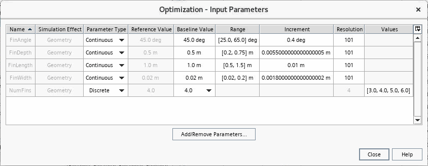
Define the input parameters that you want Design Manager to modify in the design study.
Design Manager input parameters are the parameters from the Simcenter STAR-CCM+ reference simulation that Design Manager can vary.Each study requires at least one input parameter. A DOE study requires at least two input parameters to run.For information on the supported input parameters, see Study Inputs.
To set input parameters:
For more information, see Input Parameters Reference. For guidance on specifying a list of parts for the Replace Part operation, see Substituting Geometry Parts in a Study.
-
For an
Optimization study, you can supply the optimization algorithm with guesses of good design. By this means you can potentially reduce the path from the initial to the best design. You can either enter designs manually or use designs from a previous design study.
For more information, see Seeding an Optimization Study with Predefined Designs.
-
Set the responses whose values you want
Design Manager to record at the end of each design simulation or which influence the study as objectives or constraints.
Responses represent the outputs of your design study and are based on reports from the reference simulation. Each study requires at least one response. You do not specify responses for a CAD Robustness study.
To create responses, select the node and, for Response, choose one or more reports from the reference simulation.
Alternatively, you can drag-and-drop reports from the Reports node of the reference simulation to the Responses node of the design study.For more information, see Responses Reference. -
Set the objectives of the design study.
For an Optimization study, objectives define the goals of the optimization algorithm. A Weighted sum of all objectives optimization study requires at least one objective and a Multiple objective tradeoff study (Pareto front) requires at least two objectives.
For a Sweep study, objectives are optional and only affect the performance value of the designs.
To set objectives:
- Create responses for the reports whose values drive the optimization.
- For each response, select the respective node and activate Is Objective.
- Select the node and set Goal to Maximum or Minimum.
For more information, see Objective Properties. -
If required, set the constraints of the design study.
Constraints allow you to define the design space in which acceptable designs are found.
To set constraints:
- Create responses for the reports whose values you want to constrain.
- For each response, select the respective node and activate Is Constraint.
- Select the node and set Type to the type of constraint that you want to impose, such as Maximum.
- Select the node and set the constraint value.
For more information, see Constraint Properties. -
Optionally, you can create a user response as an expression of the existing
study responses.
For more information, see Responses Right-Click Actions.
-
If required, create surrogates to use in another design study or in external
tool.
Refer to 生成和应用替代模型 for more setup details.
-
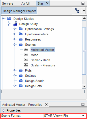
Set the scenes and plots that you want
Design Manager to export from each design simulation.
To set scenes:
For more information, see Scenes and Plots Reference. - If you want to add extra processing steps in the workflow for each design simulation, you can add Java macros that Design Manager executes for each design. You script the required steps in a Java file and add the file to the design study. Design Manager can perform these steps before meshing, after meshing, or after running. For more information, see Customizing the Workflow Using Java Macros.

