Study Inputs
In Design Manager, study inputs are parameters that you define in the reference simulation and that Design Manager can modify during design studies.
The types of Simcenter STAR-CCM+ simulation objects that can be selected as Design Manager input parameters are:
| 注 | Design Manager uses a tolerance of 1.0E-16 to compare two floating-point numbers. Before creating designs, Design Manager executes a check algorithm. Two designs are considered duplicate if all their design parameters are considered equal after the check algorithm. |
3D-CAD Design Parameters
Design parameters are used in 3D-CAD to specify characteristic dimensions of a model that can be modified outside 3D-CAD. For more information, see Design Parameters.
The design parameters that you expose in your reference simulation are available as inputs for Design Manager. Changing a design parameter pushes the modified geometry through the mesh pipeline so that the geometry is remeshed. Make sure that the specified range for the variables allows the geometry to remesh successfully. If a change to a design parameter causes the geometry to become invalid, the Design Manager analysis fails to run.
- Scalar quantities—values such as dimension distances, radii, extrusion lengths, taper angles.
- Translation components—Design Manager attempts to translate a coordinate system with the same name as the current design parameter. This feature is useful if you want to rotate a component after the translation. It is important to create the translation variables first, before any rotation variables.
CAD Client Design Parameters
Design parameters that originate from CAD Clients are also supported as input parameters. With a CAD client, you can transfer your CAD geometry and design data—such as design parameters—directly from within your CAD package environment to Simcenter STAR-CCM+. You can rename the CAD parameters or responses in Simcenter STAR-CCM+; see "Transferring Geometry to Simcenter STAR-CCM+" in the documentation for the specific CAD client. For the list of supported CAD Packages, see CAD Packages Support.
Global Parameters
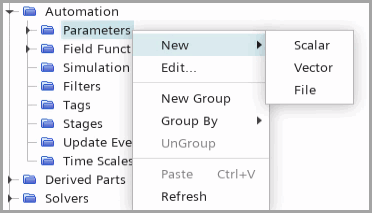
A global parameter could be a scalar, vector physical quantity (for example, 120.0 K or [0.0, 1.0, 0.0] m) or file path (replacing parts using Replace Part operation) that you define once in your Simcenter STAR-CCM+ simulation and can be used in multiple objects of the simulation.

Changing a global parameter modifies the value of the quantity that refers to the parameter. For more information, see Global Parameters.
Using global parameters, you can instruct Design Manager to control various scalar, vector and file path parameters, for example:
- Mesh values—such as the base size
- Region physics values—such as volumetric heat sources
- Boundary physics values—such as inlet velocities, turbulence scalars, or thermal scalars
- Motion parameters—such as rotation rates or translation velocities
- Part replacement—replacing parts or assemblies in a design exploration
Simulation Effect and Mesh Reuse
For each parameter, you specify whether changing the parameter value would require a change in the mesh. The Simulation Effect property value is set for each parameter in the reference simulation, and indicates how the parameter affects the simulation run. For more details, refer to 设置模拟参数的模拟效果.