Wall Boiling Model Reference
In a heated channel, where the flow at the entrance is subcooled, boiling begins when the wall temperature exceeds the saturation temperature of the liquid.
The wall boiling model predicts the amount of wall superheat, which is the amount the wall temperature exceeds the saturation temperature, as well as the axial and radial distribution of vapor. For more information, see Boiling.
| Theory | See Wall Boiling. | ||
| Provided By | |||
| Example Node Path | |||
| Requires |
A Eulerian Multiphase simulation with the following models activated:
A minimum of two Eulerian phases: one liquid phase and one gas phase. In the liquid phase, the following phase models activated:
In the gas phase, the following models activated:
A Continuous-Dispersed Topology or Multiple Flow Regime Topology phase interaction is required. In the phase interaction, the following models activated:
|
||
| Properties | Key properties are: Relaxation Factor. | ||
| Activates | Physics Models |
Wall Bubble Nucleation See Wall Bubble Nucleation Properties. Wall Transient Conduction |
|
| Model Controls (child nodes) |
Wall Dryout Area Fraction |
||
| Boundary Inputs | See Boundary Settings. | ||
| Field Functions | See Field Functions. | ||
Wall Boiling Properties
- Relaxation Factor
- Adjusts the model sensitivity. Reduce it to improve convergence.
Wall Boiling Model Controls
The following child nodes are provided:
- Wall Dryout Area Fraction
- The wall dryout
area fraction specifies how much of the heat flux that is applied at the
wall is directed towards the vapor convection, as opposed to liquid
convection and evaporation. It can be used to improve robustness during
initial convergence, or for indicating the onset of Departure from Nucleate
Boiling (DNB) conditions in converged solutions.
For more information, see Wall Dryout Area Fraction.
Wall Dryout Area Fraction Properties
- Method
-
- Basic Wall Dryout Area Fraction
-
Defines the area fraction as zero until the volume fraction of the vapor near the wall exceeds a specified value. It then transitions the area fraction to unity as the vapor volume fraction approaches unity.
To reduce grid-dependency, the near-wall volume fraction that is used for the area fraction calculation can optimally be defined as an average over a prescribed thickness of a notional bubbly layer next to the wall.
This method is the default.
- Constant, Field Function, Table, and User Code
- Standard methods provided for user-specified values.
- Wall Dryout Breakpoint
- The vapor volume fraction at which point heat transfer to the vapor phase begins (see
Eqn. (2123)). The default value is 0.9.
This property is available for the Basic Wall Dryout Area Fraction method only.
- Bubbly Layer Relaxation Factor
- Controls the update of the Bubbly Layer Volume Fraction that is used by the dryout model. It helps convergence behavior once the dryout criterion has been exceeded. The default value is 0.5.
- Bubbly Layer Option
- Defines the thickness of the layer that is used for averaging volume fraction in the dryout criterion.
Wall Bubble Nucleation Properties
The following child nodes are provided:
- Nucleation Site Number Density
- Bubble Departure Diameter
- Bubble Departure Frequency
- Lift Off Diameter (only if the Adaptive Multiple Size-Group (AMUSIG) Model or an S-Gamma Model is selected in the dispersed phase)
Nucleation Site Number Density Properties
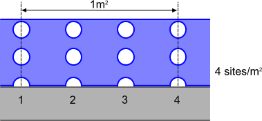
The nucleation site number density determines the number of locations on the heated surface where bubbles form, per unit area.
This is the leading factor determining the evaporation rate in a mechanistic model of subcooled boiling (see Eqn. (2110)). The diagram below illustrates this parameter:

- Method
- The options for
calculating the nucleation site number density.
- Lemmert-Chawla
- Hibiki-Ishii
- Li
- User-Defined: Constant, Field Function, Table, or User Code.
- Lemmert-Chawla Properties
-
The Lemmert Chawla model ([499]) is a correlation with wall superheat and is the default model, recommended for initial studies on the grounds of robustness. The default settings assume that the number of active nucleation sites varies with the wall superheat to the power of 1.805. This value is used within the Tolubinsky and Kostanchuk model for calculating bubble departure diameter, for example for modeling forced convection, subcooled boiling of water at 45 bar.
- Hibiki-Ishii Properties
-
The Hibiki Ishii model is a more advanced nucleation site number density model. It is applicable for pressures up to 198 bar. Use the Hibiki Ishii model with the Kocamustafaogullari model for bubble departure diameter.
The model has the following characteristics:
- It considers a boundary condition for wall superheating.
- It is validated against numerous sets of experimental data.
- It has a wide range of applicability in terms of mass flow, pressure, and contact angle.
If you use a working fluid other than water, adjust the Wall Contact Angle. If you know average cavity density and the cavity length scale values for the working surface, adjust these also.
- Li Properties
-
The Li model is based on a parametric analysis of existing experimental data. It is a function of three variables: wall superheat, pressure, and contact angle. This model is applicable for pressures ranging from 0.101 MPa–19.8 MPa.
The Li model has the same range of applicability pressure and wall superheat as the Hibiki-Ishii model. It is validated against numerous sets of experimental data, and has a wide range of applicability in terms of mass flow, pressure, and contact angle.
Bubble Departure Diameter Properties
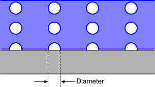
The bubble departure diameter determines the diameter of the bubble at the instant it leaves the nucleation site.
This is the second of the three factors used to determine the evaporation rate in subcooled boiling (see Eqn. (2110)). The diagram below illustrates this parameter:

- Method
- The options for
calculating the bubble departure diameter.
- Tolubinsky Kostanchuk
- Kocamustafaogullari
- Unal
- User-Defined: Constant, Field Function, Table, or User Code.
- Tolubinsky Kostanchuk Properties
-
The Tolubinsky Kostanchuk model is a correlation against liquid subcooling and is the default model that is recommended for initial studies on the grounds of robustness. It matches the default Lemmert Chawla model for nucleation site number density.
- Kocamustafaogullari Properties
-
The Kocamustafaogullari model is more recent, more general and based on a force balance with an adjustment for pressure dependence. This model must be used whenever the Hibiki Ishii model is selected for nucleation site number density.
- Unal Properties
-
The Unal model is suitable for both low-pressure and high-pressure boiling scenarios. No parameter tuning is required. You can obtain better predictions if you also model the bubble size distribution, breakup, and coalescence.
- Reference Diameter Subcooling
- Reference diameter subcooling (that is, the difference between the saturation temperature and liquid temperature for the reference diameter) used when calculating the bubble departure diameter at the given value of subcooling. This value is in Eqn. (2153).
- Minimum Diameter
- Sets the lower limit for the bubble departure diameter. This setting makes sure that the result is within plausible limits.
- Maximum Diameter
- Sets the upper limit for the bubble departure diameter. This setting makes sure that the result is within plausible limits.
Bubble Departure Frequency Properties
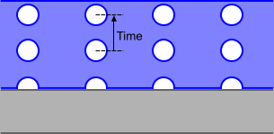
The bubble departure frequency determines how many bubbles leave a nucleation site per second.
This is the last of three key factors determining the evaporation rate in subcooled boiling (see Eqn. (2110)). The diagram below illustrates this parameter:

- Method
- The options for
calculating the bubble departure frequency.
- Cole: This frequency is equivalent to a terminal velocity scale over bubble departure diameter, and the overall evaporation rate is calibrated around this assumption (see Eqn. (2155)). There are no adjustable parameters, but you can define an alternative model.
- User-Defined: Constant, Field Function, Table, or User Code.
Lift Off Diameter Properties
For the Adaptive Multiple Size-Group (AMUSIG) Model or an S-Gamma Model selected in the dispersed phase, the lift off diameter determines the diameter of the bubbles as provided to the respective particle size distribution model at the wall. Corresponds to in Eqn. (2306).
- Method
- The options for
calculating the lift off diameter.
- Bubble Departure Diameter: sets the lift off diameter equal to the specified Bubble Departure Diameter.
- Field Function: allows you to specify a different wall bubble diameter for the size distribution model than for the wall boiling model.
Wall Transient Conduction Properties
This model corrects the Bubble Induced Quenching Heat Flux so that it uses the temperature of the liquid brought to the wall by the action of the departing bubble. This temperature can be different to the liquid temperature computed at the cell center next to the wall. The correction is taken from a location on the undisturbed liquid phase temperature profile away from the departure site.
- Quenching Temperature Option
- Defines the location for sampling the liquid temperature profile.
The following child nodes are provided:
- Bubble Influence Wall Area Fraction
- Bubble Induced Quenching Heat Transfer Coefficient
Bubble Influence Wall Area Fraction Properties
The bubble influence wall area fraction estimates the fraction of the wall area that is affected by the sweep of liquid inflow beneath a departing bubble.
- Method
- The options for
calculating the bubble influence wall area fraction.
- Kurul Podowski
- User-Defined: Constant, Field Function, Table, or User Code.
- Kurul Podowski Properties
-
The Kurul Podowski model assumes that the wall area influenced by bubble-induced quenching is larger than the nucleation site area, by a specified factor (see Eqn. (2158)).
Bubble Induced Quenching Heat Transfer Coefficient Properties
When a bubble leaves the heated surface, cooler liquid fills the space that it occupied. The heat transfer during this process is known as quenching heat transfer. The Quenching Heat Transfer Coefficient is used to calculate the quenching heat flux.
- Method
- The options for
calculating the bubble induced quenching heat transfer coefficient.
- Del Valle Kenning
- User-Defined: Constant, Field Function, Table, or User Code.
- Del Valle Kenning Properties
-
This model calculates the bubble induced quenching heat transfer coefficient using Eqn. (2156).
Boundary Settings
The following settings are available for wall boundaries.
- Phase Conditions
-
Available for the Unal bubble departure diameter model only, under .
- Surface Conductivity
- The thermal conductivity of the wall surface. This value is in Eqn. (2154).
- Surface Density
- The density of the wall surface. This value is in Eqn. (2154).
- Surface Specific Heat
- The specific heat of the wall surface. This value is in Eqn. (2154).
- Physics Conditions
-
- Wall Interphase Mass Transfer Option
- Activates interphase mass transfer interaction on the wall boundary.
Field Functions
- BubblyLayerVolumeFraction
- in Eqn. (2122).
- BubblyLayerVolumeFractionGradient
- in Eqn. (2122).
- BubbleDepartureDiameter
- in Eqn. (2150) for the Tolubinsky Kostanchuk model or Eqn. (2152) for the Kocamustafaogullari model.
- BubbleDepartureFrequency
- in Eqn. (2155).
- BubbleInfluenceWallAreaFraction
- in Eqn. (2158).
- BubbleInducedQuenchingHeatTransferCoefficient
- in Eqn. (2156).
- BubbleInducedQuenchingTemperatureFactor
- in Eqn. (2117).
- BubbleInducedQuenchingTemperatureDistance
- in Eqn. (2117).
- Nucleation Site Number Density of [phase interaction]
- in Eqn. (2128) for the Lemmert Chawla model, in for the Li model, or Eqn. (2132) for the Hibiki-Ishii model.
- WallInterfaceMassFlux
- in Eqn. (2115).
- BoundaryHeatFlux<Liquid Phase Name>
- in Eqn. (2119).
- BoundaryHeatFlux
- in Eqn. (2120).
- BoundaryHeatFlux<Vapor Phase Name>
- in Eqn. (2121).
- InterphaseMassTransferRate
-
The mass transfer between phases due to a single reversible process, such as Bulk Boiling or Species Dissolution. This value is positive when the mass transfer is towards the first phase in the interaction. For continuous-disperse interactions, the first phase is the continuous phase. If the continuous phase is the liquid phase in a boiling problem, a positive rate signifies condensation and a negative rate signifies evaporation.