Blade Element Method
The blade element method formulation is based on the methodology that is proposed by Rajagoplan [279] and others. It is primarily designed to model the effects of a helicopter rotor on the flow field without actually prescribing the exact geometry of rotor blades.
This approach consists of two parts. The first step is to identify the location of cells within the computational domain that belong to the virtual disk and to which the source term is applied. The second step involves the calculation of the momentum source term vector for each cell, which was identified and marked in the first step.
Step 1: Cell Marking and the Allocation to the Blade Elements/Buckets Based on the Interpolation Grid
The information for this step is user-specified and provided through the virtual disk nodes:
- Disk Geometry
Describes the geometrical dimensions and the orientation of the disk
- Virtual Disk Resolution
Specifies the size of the two-dimensional interpolation grid in polar coordinates, representing the actual blade elements. The blade properties such as chord, twist, and aerodynamic characteristics prevail throughout the whole element.
Source Term Distribution: Time Averaged
For the Time Averaged approch, the source term is calculated per blade element on the interpolation grid and then transferred to the finite volume mesh. Each element is associated with a number of cells on the finite volume mesh. For the coupling between the local flow conditions and the modeled rotor, the information is taken from the finite volume cell which is the closest to the center of a blade element on the interpolation grid. Thus, the specified size of the interpolation grid is the actual computational effort of the influence of the rotor on the flow field. The sketch below explains the flow field coupling between the finite volume mesh (red) and the virtual disk interpolation grid (black).
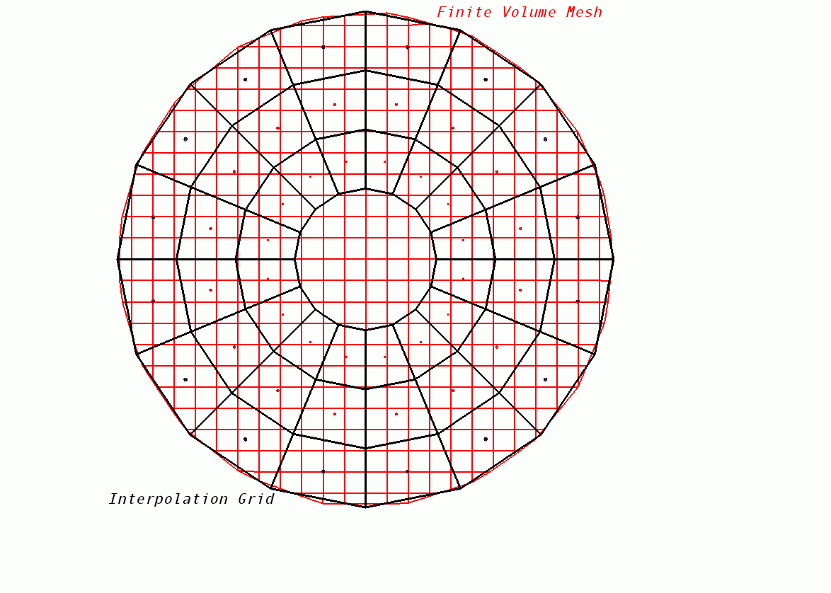
The marking procedure is itself a two-step procedure. First, all the cells that fall within the circular disk area are marked to receive the source term. Second, each of the marked cells is assigned a bucket/element number corresponding to its location with respect to the interpolation grid. So each of the cells that was marked during the first step belongs to one of the elements/buckets of the interpolation grid.
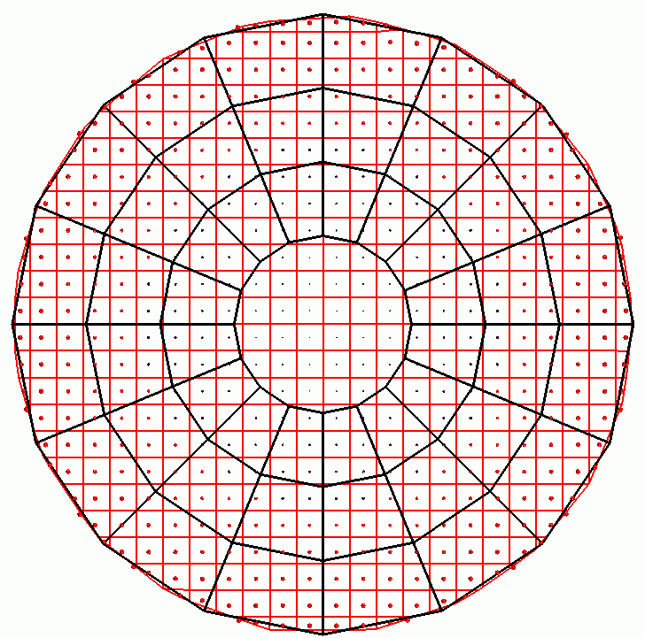
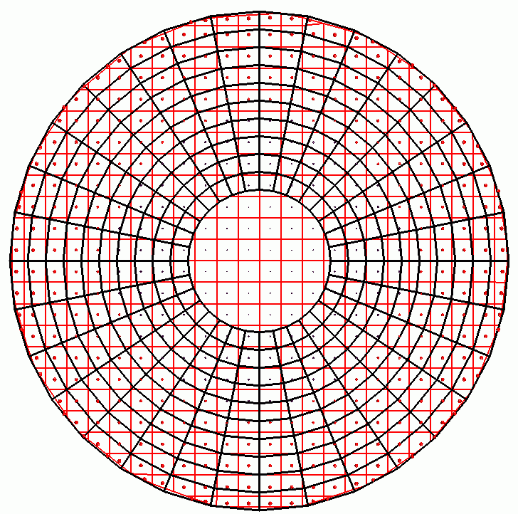
This approach requires that each element/bucket has at least one cell in its domain. If the finite volume mesh is very coarse and the interpolation grid is too fine then, you are asked to reduce the resolution. The following two figures show the interpolation grid for two different resolutions. For the fine interpolation grid in the second figure, no finite volume cell come under the domain of some for some of the elements/buckets at the innermost radius.
Source Term Distribution: Time Accurate
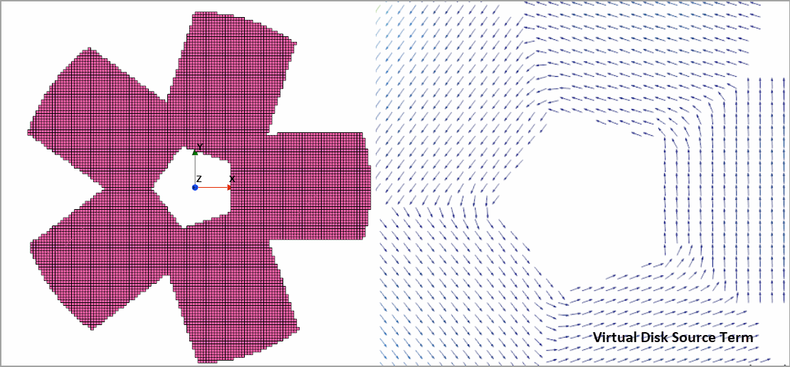
The Time Accurate approach tracks the motion of the blades and adds source terms only to the volume cells which correspond to the location of the blades. For a rotor with four blades, the cells are marked as shown below according to the blade shape and location specified within the Disk Geometry node.
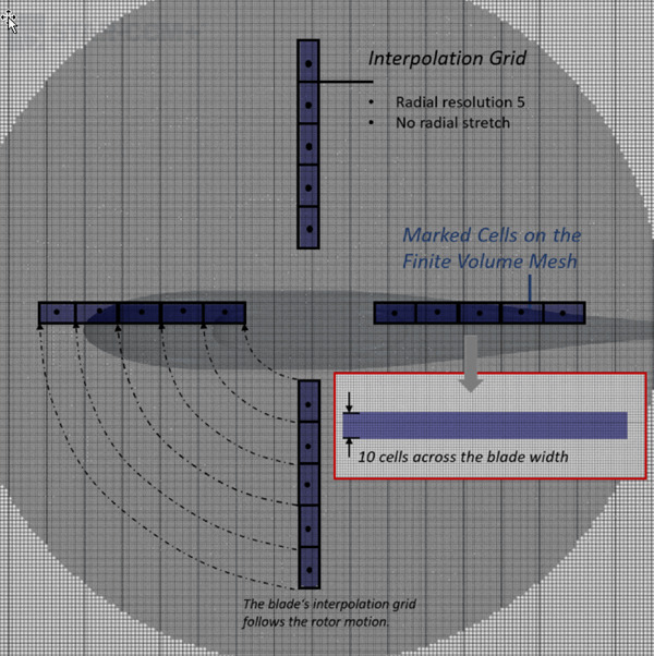
To ensure successful coupling with the interpolation grid, the finite volume mesh must be sufficiently fine that at least 5 cells are marked across the blade width. A similar mesh resolution should be applied for the entire sweep area of the rotor. In the example above, 10 cells are marked.
With the default interpolation mode, Simcenter STAR-CCM+ supports overlapping of the marked cells of different blades. The source term is computed accordingly:
Step 2: Calculation of Momentum Source Term Strength
The second part of the blade element method calculates the strength of momentum source term for the elements on the interpolation grid. Based on the geometry of the rotor (that is orientation and origin), a disk local cartesian coordinate system is created. This cartesian coordinate system has its origin at the center of the rotor and the -axis in the direction corresponding to the thrusting direction of the disk. The -axis is perpendicular to the plane of rotation, while the and axes lie in the plane of the disk. The following sketch demonstrates the disk local coordinate system:
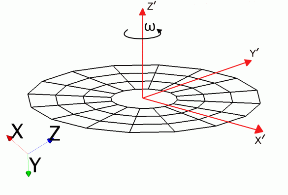
The rotational speed is always oriented along the -direction. + corresponds to a counter-clockwise wise (CCW) rotation and - corresponds to a clock-wise (CW) rotation when viewed from the + direction.
To account for blade flapping, two additional coordinate systems are defined:
- A rotor-based cylindrical system with respect to the basis of the local coordinate system
- A Cartesian coordinate system with respect to the basis of the cylindrical coordinate system. It is called the flap coordinate system.
The basis of the flap system is defined such that points in the spanwise direction of the blade. The basis vector of the flap coordinate system points in the same direction as of the rotor-based cylindrical system. The cylindrical system rotates with the blade and the flap system is tilted with respect to the cylindrical system. Given the azimuth location of the blade, the cylindrical system is rotated such that is aligned with the blade span. The flap system is tilted by , that is, by the flap angle of this azimuth location. All calculations are performed in the flap system. The resulting force vector is transformed back to the lab system and then added to the momentum equation as a source term.
The local flow field velocity in the laboratory coordinate system is:
The local flow velocity is transferred to the flap coordinate system using a sequence of transformation matrices :
The blade has a velocity due to rotation, which can be written in the flap coordinate system as:
where is the radius vector.
The velocity relative to the blade is thus given by:
- induced angle of attack (inflow angle)
- blade flap angle
- geometrical pitch angle
- geometrical twist angle
The induced angle of attack is now calculated as:
where the direction of in the reverse flow region for high advance ratios is taken into account by the .
It can be seen from Eqn. (4996) that the blade flap angle affects the inflow angle (induced angle of attack) through the blade flap velocity, and thus the effective angle of attack .
The pitch angle is defined as:
where is the azimuth angle, is the collective pitch angle, is the lateral cyclic pitch angle, and is the longitudinal cyclic pitch angle.
The final effective angle of attack is then calculated as:
Knowing the angle of attack and the blade relative velocity experienced by the airfoil, either the Mach number or the Reynolds number are calculated. The aerodynamic force coefficients are also used to calculate the Mach and the Reynolds number. You specify these coefficients in the form of tables in the simulation tree. Which number is calculated depends on how you specify the aerodynamic force coefficients—as a function of Mach number , or as a function of Reynolds number.
The lift and drag forces are then computed as:
where is the blade chord.
To account for tip-loss due to trailing vortices at the tip of a rotor blade, the lift force , the angle of attack or lift and drag are corrected depending on the chosen tip correction method.
The forces are then converted into the normal and tangential force (transformation from the wind axis to the rotor flap system):
As there are no aerodynamic forces along the blade span, . The resultant aerodynamic force vector can be assembled on the blade element as in the flap system.
Finally, the force vector is transformed into the laboratory coordinate system:
The instantaneous force acting on the fluid element is then .
The time-averaged source terms are added to the discretized momentum conservation equations. Since the blade only spends a finite fraction of its total revolution time passing through the control volume, the time-averaged source terms are scaled by the time fraction:
where is the number of blades and is the angular distance through which the blade traverses in passing through a blade element.
The time-accurate source terms do not require any scaling. The specific source term from a given blade element is distributed over the respective cells in the finite volume mesh, proportional to their cell volume.
Numerical Trim Algorithm
- Main Rotor Controls
Generally, a helicopter has four independent controls: three for the main rotor and one for the tail rotor. In the Simcenter STAR-CCM+ implementation, the rotor is treated in isolation and only the rotor controls are considered.
The main rotor controls are:
- Collective pitch:
By using this control, a pilot can change the pitch angle of all the blades of the main rotor collectively, that is, by the same amount. This change effectively influences the total thrust generated by the main rotor.
- Cyclic pitch:
By using this control, a pilot can change the pitch angle once per revolution. The cyclic pitch is categorized as follows:
- Lateral cyclic pitch :
Varies as per . The lateral cyclic pitch is at a maximum or minimum when a blade is at 0° and 180°. The rotor response, which is phased by 90°, leads to a control effect in the lateral direction (y-axis) and effectively influences the roll moment.
- Longitudinal cyclic pitch
Varies as per . The longitudinal cyclic pitch is at a maximum or minimum when a blade is at 90° and 270°. The rotor response, which is phased by 90°, leads to a control effect in the longitudinal direction (x-axis) and effectively influences the pitch moment.
- Lateral cyclic pitch :
The total pitch angle therefore is a function of the azimuthal angle and is given by:(5002)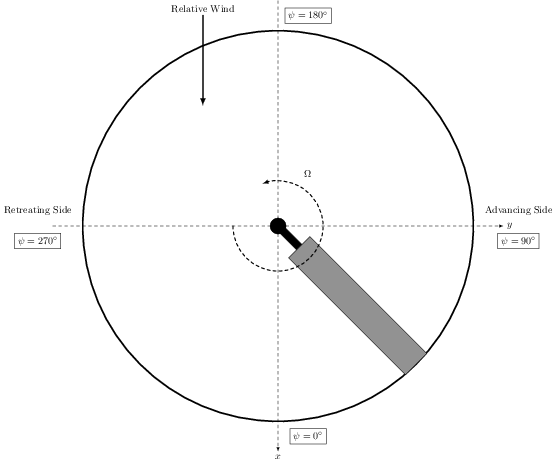
- Collective pitch:
- Algorithm
- The rotor aerodynamic response is a highly coupled function of its control inputs and its aerodynamic environment. Although the thrust generated by rotor is mainly influenced by collective pitch, it is also influenced by the cyclic pitch inputs. Likewise, the roll and pitch moments are directly linked to cyclic pitch inputs but also produce a change in thrust. Defined in the local coordinate system of the virtual disk:(5003)
where is the thrust, is the roll moment, and is the pitch moment.
This coupled system of equations can be interpreted as how the control input vector is related to the rotor response vector where:
Each flight condition corresponds to a state of the rotor response vector , which requires a particular state of the control input vector , which in turn affects the aerodynamic characteristics of a helicopter.
To investigate the aerodynamic performance of a helicopter, you first choose a flight condition. This means that the response vector is known, but not the control input vector . You start the iterative procedure with an initial guess of the input vector . is then iteratively updated until the solution converges towards the target response vector .
For the iterative procedure to update , the coupled system of equations is linearized. Then the Newton-Raphson approach is applied. To linearize, the Taylor series expansion for about is applied:(5004)Considering only the first-order terms, Eqn. (5004) is rearranged to read:(5005)where is the Jacobian matrix of the dependent quantities, that is, of the response vector with respect to the control inputs .
Eqn. (5005) is rewritten to:(5006)In Eqn. (5006), the subscript (i) corresponds to the ith trim iteration and d corresponds to the desired target state of the rotor response vector .
The initial guess for , yields an initial , which is usually not equal to the target state of . To proceed with the trim iteration, the Jacobian matrix must be determined using a frozen flow field. To achieve this, each component of the control input vector is independently perturbed and the rotor response is recomputed. The partial derivatives are then computed using 2nd-order central differences. With available, the correction to the control input vector is determined by solving Eqn. Eqn. (5005). The computed correction is under-relaxed to achieve numerical damping and is then used to update the control input vector. The procedure is repeated until the solution converges towards the target within a specified tolerance.
In time-average mode, the control input correction is applied repeatedly. The convergence of the source term triggers the application of the correction.
In time-accurate mode, the rotor runs at initial condition for a few revolutions until flow is periodic. Before applying the control input correction, the trim solver collects the data of for one revolution to build average values. The event of application is steered by either the convergence of the source term or by the number of revolutions between two corrections, which are specified in the Trim Option properties.
- Overview of the Source Term Update
The following flowchart provides an overview of the blade element source term update process. This procedure is triggered when the main flow solver is ready to accept source term contributions from optional models into the momentum equation. When the main flow related fields such as pressure and velocity are available, the blade element source term is evaluated.
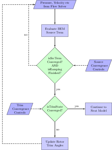
Next, Simcenter STAR-CCM+ checks if the blade element source term is converged up to the Source Tolerance (see User Guide > Modeling Physics > Virtual Disk Model > Blade Element Method > Setting the Source Convergence Control). Furthermore, Simcenter STAR-CCM+ checks if the ramping of the rotation rate is finished. If either of the checks fails, the blade element source term is under-relaxed by the Source Under Relaxation Factor (see see User Guide > Modeling Physics > Virtual Disk Model > Blade Element Method > Setting the Source Convergence Control) and is added to the source term of the momentum equation. The solution process then continues with the next model. This step corresponds to the no branch of the first decision block in the flow chart above.
When the first decision block evaluates to yes, Simcenter STAR-CCM+ checks if the main rotor response equals the target values. This check corresponds to the second decision block in the flow chart above and is interpreted as the convergence of the trim state. The trim state is converged if the user-specified Trim Tolerance is reached (see User Guide > Modeling Physics > Virtual Disk Model > Blade Element Method > Setting the Trim Convergence Control). If the trim state is converged, the solution process continues with the next model. If the trim state is not converged, the rotor trim angles are updated according to the numerical trim algorithm. The computed trim angles are under-relaxed by the Trim Under Relaxation Factor (see User Guide > Modeling Physics > Virtual Disk Model > Blade Element Method > Setting the Trim Convergence Control).
The source term computation is performed at each iteration. Therefore, any changes in the user setup resulting in a different flow field, influence the blade element method source term vector. It is important to note that the trim algorithm is executed only after the blade element source term has converged to the specified level. If the external flow field is of highly unsteady nature, you are recommended to relax the convergence tolerance on the source term so that the trim angle update can spring into action. For extreme case, where the main rotor is operating in a wake and the desired flight condition is hover, you are advised to deactivate the source term convergence check by specifying a tolerance level of 100%. This setting ensures that the algorithm is executed at each iteration.