SPH Boundary Conditions
To complete the mathematical model, you specify conditions on the solution domain boundary.
Wall
A wall boundary represents an impermeable surface.
When a particle is close to a wall, and the wall extends beyond the kernel support, consistency is maintained by filling the kernel support with neighboring particles. This is achieved by introducing ghost particles on the wall. A term is added to the derivation operators to account for the ghost particles.
The pressure gradient is given by:
The velocity divergence is computed as:
The summation is over fluid particles and is over ghost particles.
To apply the boundary conditions, the ghost particle pressure and velocity for are given by:
where is the resultant of the body forces and is the wall velocity.
- No-Slip Wall
-
At the no-slip wall, the fluid sticks to the wall and moves with the same velocity as the wall. Therefore, for no-slip stationary walls, the fluid has zero velocity at the wall. For viscous flows, the no-slip condition is applied by default.
- Slip Wall
-
The slip wall represents an impenetrable but traction-free surface.
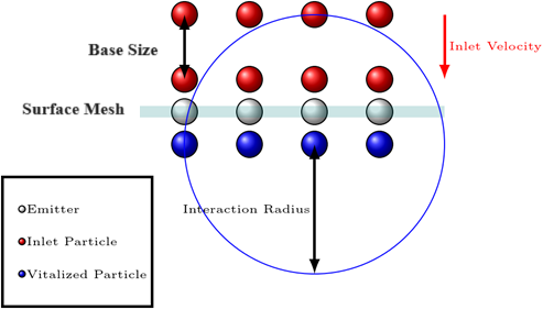
Inlet
The following image illustrates the basic concept of the velocity and mass flow inlet methodology. The emitter particles (grey) correspond to surface mesh locations where fluid is introduced. These particles follow the mesh motion. Inlet particles (red) interact with the fluid domain within an interaction radius at varying distances behind each emitter particle. Initially, the inlet particles move with a prescribed inlet velocity or mass flow. After these particles move beyond the emitter, they activate and integrate into the fluid simulation. The injection direction is oriented with the boundary normal.
- Mass Flow Inlet
- The mass flow inlet boundary specifies the known mass flow rate or the mass flux (mass flow rate per unit area) at a boundary. This boundary condition is designed for specifying mass flow inward across the boundary.
- Velocity Inlet
- The velocity inlet boundary specifies the known inflow velocity. This boundary condition is designed for specifying flow inward across the boundary.