Signal Processing Concepts
Signals can be expressed as oscillating changes of signal strength over time or as a function of signal strength over a range of frequencies. Both methods have their uses. Information can be converted from one form to the other by Fourier transforms.
Time and Frequency Domains
It is a property of all real waveforms that they can be made up of a number of sine waves of certain amplitudes and frequencies. Viewing these waves in the frequency domain rather than the time domain can be useful in that all the components are more readily revealed.

Each sine wave in the time domain is represented by one spectral line in the frequency domain. The series of lines describing a waveform is known as its frequency spectrum.
The Fourier Transform
The conversion of a time signal to the frequency domain (and its inverse) is achieved using the Fourier Transform as defined below.
This function is continuous and in order to use the Fourier Transform digitally a numerical integration must be performed between fixed limits.
The Discrete Fourier Transform (DFT)
The digital computation of the Fourier Transform is called the Discrete Fourier Transform. It calculates the values at discrete points (mΔf) and performs a numerical integration as illustrated below between fixed limits (N samples).
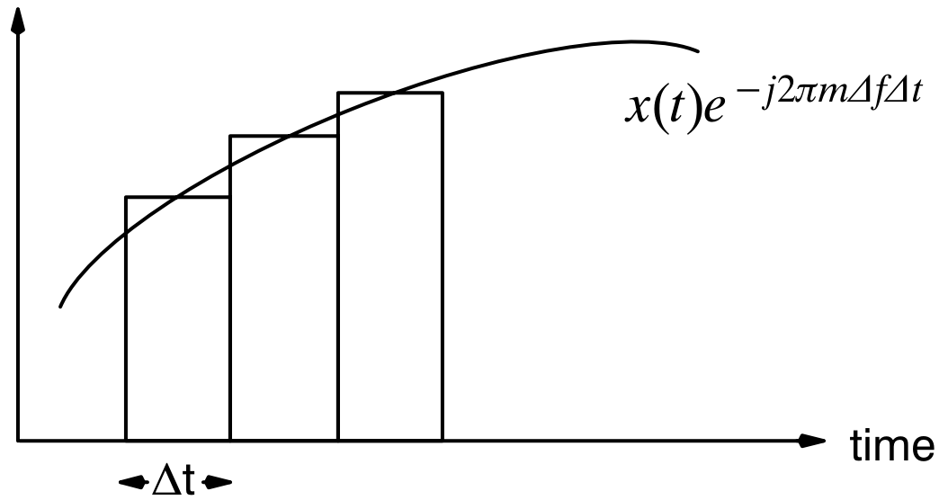
Since the waveform is being sampled at discrete intervals and during a finite observation time, there is no exact representation in either domain. This condition gives rise to shortcomings which are discussed later.
The Fast Fourier Transform (FFT)
The Fast Fourier Transform is a dedicated algorithm to compute the DFT. It thus determines the spectral (frequency) contents of a sampled and discretized time signal. The resulting spectrum is also discrete. The reverse procedure is referred to as an inverse or backward FFT.
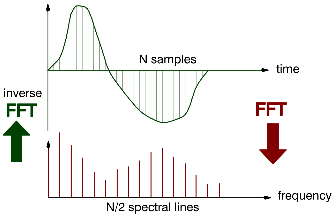
To achieve high calculation performance, the FFT algorithm requires that the number of time samples N is a power of 2 (such as 2, 4, 8, …, 512, 1024, 2048).
Blocksize
Such a time record of N samples is referred to as a block of data with N being the blocksize. N samples in the time domain converts to N/2 spectral (frequency) lines. Each line contains information about both amplitude and phase.
Frequency Range
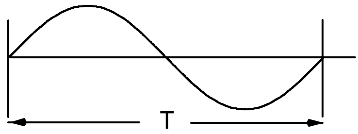
The time taken to collect the sample block is T. The lowest frequency that can be detected, then, is that which is the reciprocal of the time T.
The frequency spacing between the spectral lines is therefore 1/T, and the highest frequency that can be determined is (N/2) · (1/T).
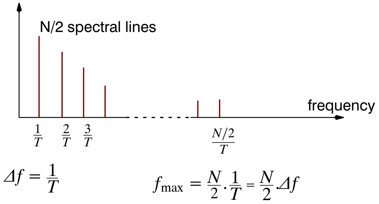
The frequency range that can be covered is dependent on both the blocksize N and the sampling period T. To cover high frequencies, you need to sample at a fast rate, which implies a short sample period.
Leakage and Windows
A further problem associated with the discrete time sampling of the data is that of leakage. A continuous sine wave such as the one shown below should result in the single spectral line.
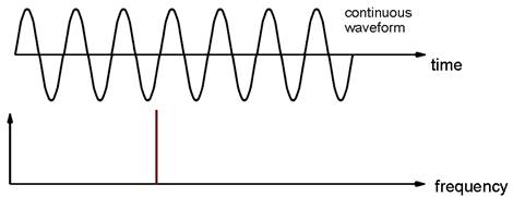
Because the signals are measured over a sample period T, the DFT assumes that this is representative for all time. When the sine wave is not periodic in the sample time window, the result is a consequent leakage of energy from the original line spectrum due to the discontinuities at the edges.
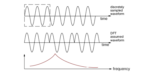
The user should be aware that leakage is one of the most serious problems associated with digital signal processing. While aliasing errors can be reduced by various techniques, leakage errors can never be eliminated. Leakage can be reduced by using different excitation techniques and increasing the frequency resolution or through the use of windows as described below.