Defining Linear Elastic Materials
Linear elastic materials deform elastically under loading, returning to their original shape when the load is removed. In general, you can use a linear elastic description for modeling most metals, provided that the stress on the material is below the yield stress.
Linear elastic materials obey Hooke's law, which defines a linear stress-strain relationship. For more information, see Linear Elastic Materials.
By default, Simcenter STAR-CCM+ treats the solid materials as compressible. Linear elastic materials are considered incompressible when their Poisson's ratio . If, in any direction, , activate the Nearly Incompressible Material model in the solid stress physics continuum.
The Linear Elasticity model cannot be used if you have selected both the Nearly Incompressible Material and Nonlinear Geometry models in the solid physics continuum. In this case, select the Hyperelasticity model.
To define a linear elastic material:
- Create a material law and assign it to the relevant solid materials, as explained in Defining the Solid Materials.
- Right-click the node and choose Select models...
-
In the
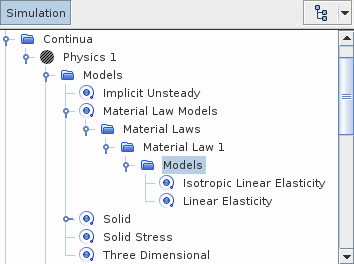
Material Law 1 Model Selection dialog, activate the following models:
Group box Model Material Stiffness Models Linear Elasticity Material Strain Measures- To model linear geometries, activate Linear Strain (Small Strain).
- To model nonlinear geometries, activate Green-Lagrange (Small Strain).
Linear Elastic Material Models - To model materials that have the same mechanical properties in all directions, activate Isotropic Linear Elastic.
- To model materials that have independent mechanical properties along three mutually-orthogonal directions, activate Orthotropic Linear Elastic.
- To model materials that have independent mechanical properties in all directions, activate Anisotropic Linear Elastic.
For more information, see Linear Elastic Materials.


- For each region, select the node and set Orientation to the
appropriate coordinate system. For more information, see Orientation Manager and Local
Orientations.
You can visualize the material coordinate system in a scene using the basis vector field functions. See Local Material Coordinate System.
This step is not required for isotropic materials, as their properties are the same in all directions.
-
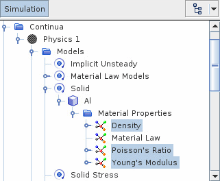
Define the material properties as required. For each material:
-
If required, continue by defining any thermal properties. See
Defining Thermal Properties.
For more information, see Material Properties.
Optionally, you can account for plastic yield. For instructions, see Defining Elastoplastic Materials.