Defining the Regions Layout
Create the required regions, boundaries, and interfaces.
-
Assign the geometry parts representing the solid structure to a region, creating appropriate boundaries and interfaces.
- If the simulation contains a fluid part for Fluid-Structure Interaction (FSI) or Conjugate Heat Transfer (CHT), assign it to a separate region and create the fluid-structure interface as a contact-mode interface (in the Assigns Parts to Regions dialog, choose Create Contact-mode Interfaces From Contacts ).
- If the solid part has periodic contacts for cyclic symmetry (see Preparing the Geometry), create an interface from each periodic contact.
- For simulations with a large
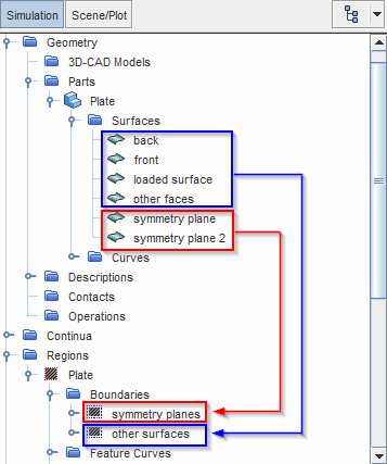
number of parts, keep the number of boundaries and interfaces to a
minimum. For the solid region, you can assign part surfaces that are
subject to different loads and constraints to the same boundary, as
loads and constraints are defined directly on part surfaces, curves, and
points. In most cases, the solid region requires two boundaries—one
boundary for all part surfaces representing symmetry planes, and one
boundary for the remaining part surfaces.
In general, it is good practice to assign the surfaces that belong to an interface to a separate boundary. This practice is useful when troubleshooting interface issues, as you can check whether the boundary faces are correctly mapped to the interface boundary.

For instructions on creating regions, boundaries, and interfaces, see Regions Layout Workflow.注 When you import a CAE model, Simcenter STAR-CCM+ automatically creates corresponding regions and boundaries. For regions associated with imported CAE models, you can combine boundaries as outlined in the example above. -
For each solid boundary, set
Type to either
Wall or
Symmetry Plane. See
Boundary Types.
Simcenter STAR-CCM+ automatically constrains part surfaces that are assigned to symmetry boundaries, preventing displacement in the normal direction. See Applying Constraints.
If you created any interfaces:
-
For each
node, set
Type to one of the following:
Mapped Contact Interface This type of interface supports both conformal and non-conformal mesh and is suitable for: - solid/solid interfaces
- fluid/solid interfaces for FSI and CHT applications (see Modeling FSI)
- periodic interfaces
Contact Interface These types of interface require a conformal mesh and are suitable for simulations that combine solid stress and electromagnetic models. See Selecting Solid Stress Physics Models. Not suitable for FSI or CHT interfaces.
Can be used for periodic interfaces, provided that the mesh is conformal.
An Internal internal is the only interface type supported between shell regions.
Internal Interface -
Select the node and specify the interface Topology.
The Finite Element Solid Energy model does not support repeating interfaces.
If you created any periodic interfaces:
- Select the node and set Topology to Periodic.
-
Select the
node and define the transformation as required. For more information on the available properties, see
Periodic Interface Topology.
Simcenter STAR-CCM+ always treats periodic interfaces between solids as Bonded, that is, the contacting surfaces undergo continuous displacements. See Interface Settings.
For finite element thermal analysis using shell parts, you
connect the shell parts using internal interfaces only.
-
To create the internal interfaces:
- Right-click the node and select .
- In the Create Zip Edges Operation window, select the connected shell parts.
- Select the node and set Zip Mode to New Description - Discrete.
- Right-click the Zip Edges operation and select Execute.
- Multi-select the required shell boundaries.
- Right-click one of the selected boundaries and select Create Interface.
A new internal interface is created under the Interfaces node. Before proceeding with the simulation set up, ensure the Topology is In-Place and the Connectivity is Conformal. To ensure a conformal mesh is maintained at the interfaces, mesh shell parts that share an internal interface using the same Automated Mesh (Shell) operation.