Modeling Nonlinear Geometry
By default, the Solid Stress model accounts for linear geometry phenomena. This section describes the additional steps that are required to model phenomena for which the strain-displacement relationship is nonlinear, such as applications involving large displacements or rotations of the solid structure.
-
Run a linear analysis first and check the results. If either of the following occurs you require a nonlinear analysis to obtain a more realistic solution:
- the deformations are large, that is, displacement magnitudes exceed the model dimensions by 10% or part rotations are greater than 4°
- the structure presents slender parts loaded in tension or compression
To model nonlinear effects:
-
In the physics continuum for stress analysis, activate the
Nonlinear Geometry model.
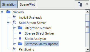
Simcenter STAR-CCM+ adds the Stiffness Matrix Update control under the Solid Stress Solver node.

-
In the physics continuum, activate an appropriate
Time model, based on the type of analysis (static or dynamic) and loading method. As a guideline, ramp loads with time-dependent functions, instead of iteration-dependent functions:
- In dynamic analyses, activate the Implicit Unsteady model.
- In static analyses with small
nonlinearities, you can apply loads in one step. In this case, activate
either the Steady model, or the Implicit
Unsteady model in Static Analysis
mode.
The second method allows you to run a static analysis while ramping the applied loads using time-dependent functions. This method is only suitable for cases with very small nonlinearities.
- In static analyses with large nonlinearities, activate the Steady model.
If you want to include the effects of Coriolis force due to the
deformation of the body:
-
In the physics continuum, activate the Coriolis - Solid Displacement
Velocity Effect model.
The deformation dependence of the other inertial load contributions (Centrifugal and Euler force) is included when the Nonlinear Geometry model is selected. For more information, see Inertial Loads.
Simulations with large nonlinearities generally require load ramping, so
that the loads are gradually applied in several steps. In this case:
- Activate the Solid Stress Load Step solver and define the ramping details. For instructions, see Load Stepping: Applying Loads Progressively.
To solve the nonlinear equations,
Simcenter STAR-CCM+ updates the stiffness matrix using Newton iteration methods. To specify the stiffness matrix update method:
-
Select the
node and set
Method to either
Full Newton or
Modified Newton.
You are advised to use the Modified Newton method only for moderately nonlinear applications. For more information, see Nonlinear Geometry Model Reference.
In nonlinear simulations, pressure and traction loads generally depend
on the deformation of the surface, and therefore on the solution. To improve the
convergence of simulations involving large, load-induced deformations, you can
activate load linearization:
-
Expand the node, then:
- In FSI simulations, select the node and activate Linearize Load.
- In solid-only simulations, select the relevant node and activate Linearize Load.
For more information, see Nonlinear Geometry Model Reference.
You are advised to adjust the default stopping criteria based on the grade of nonlinearity:
- Edit the Stopping Criteria node.
- If you are using the Implicit Unsteady solver, you are advised to set the Maximum Inner Iterations to a number between 10 and 30.
- You are also advised to increase the minimum limit for the convergence criteria, Displacement Criterion and Force Criterion, to 1E-8 or higher, in case the default values are too tight for nonlinear applications.
-
After you made the changes to the linear analysis, to take into account nonlinear geometry effects, clear the solution and run the simulation.
Large load increments or large temperature increments can cause large distortions of elements and therefore a singular stiffness matrix. This situation leads to failure of the direct solver with an error message about a negative pivot. In these cases, reduce the simulation time-step, clear the solution and run the simulation again.
True instabilities of a structure, such as buckling, can also result in a singular stiffness matrix. These problems require a good understanding of buckling loads and shapes.