Surface Mesher Controls and Values
This section details the controls and values for all surface meshers.
Alignment Location
This control aligns the wrapper mesh lines relative to the global Cartesian system. That is, you can direct the mesh lines along the x-, y- and/or z-direction.
This facility is useful when wrapping multiple regions; and the alignment of each wrapped mesh to its neighbor is important for merging and interfacing purposes.
Alignment Location Properties
- Location
- Specifies the location for aligning the wrapper mesh lines. The current scene highlights the current location of the mesh alignment point with a circular ball.
Auto-Repair Minimum Proximity
| 注 | The default value of 0.05 is suitable for most cases. This means that any two faces cannot be closer than 5% of the average edge length for the initial face. |
Auto-Repair Minimum Proximity Properties
- Minimum Proximity
- Minimum allowable distance between two faces before Simcenter STAR-CCM+ invokes automatic surface repair. A value of zero deactivates this property.
Base Size
The Base Size is a characteristic dimension of the model that you set before using any relative values. As general examples, you can set the base size to the diameter of an inlet, the length of the fluid volume, or a size that is convenient for scaling other values.CAD Projection
This control allows the mesher to project vertices back to the imported CAD surface during surface wrapping or surface remeshing. This capability results in a surface definition that is closer to the CAD geometry.
CAD projection is only available for the following CAD file types:
- Native CAD Formats
- Parasolid Transmit
- IGES
- STEP
- VDA
Projection back to an underlying CAD edge is possible only for feature edges that the surface import process defined.
For the wrapper, you can expect 20% or more CPU time for CAD projection. For the remesher, you can expect 300% or more CPU time.
| 注 | The surface wrapper cannot project some vertices, such as areas of gap closure or non-CAD data. The Output window provides a summary of the projected vertices at the end of the surface wrapping process. |
CAD Projection Properties
- Project to CAD
- When activated, projects the mesh vertices to the original CAD surface. For the majority of cases, this leads to a higher fidelity mesh, however, the mesher execution time increases. This property is recommended for cases containing a poor quality surface tessellation.
Edge Proximity
Edge Proximity allows you to specify a target minimum number of mesh faces that you require between opposing perimeter edges on a remeshed part surface.
To apply edge proximity refinement, Simcenter STAR-CCM+ first calculates the distance between opposite perimeter edges on the input part surface. This distance is divided by the specified target number of faces. The result is then set as a target size for faces on the part surface. Assuming that this target size is greater than the Minimum Size, and less than the current target mesh size, the triangulation on the part surface shows refinement after remeshing.
If one part surface defines an entire geometry part, applying edge proximity has no effect since there are no surface edges present. You can either:
- Split the part surface appropriately and apply edge proximity to the required part surfaces.
- Use the Include Feature Edges option.
Edge Proximity is only available as a custom control for an automated mesh operation and is deactivated by default.
Edge Proximity Properties
- Number of Faces
- The target number of mesh faces on the surface between each given boundary.
- Enable Search Ceiling
- Allows you to specify a Search Ceiling distance. Surfaces with a proximity distance that is larger than this value are excluded from processing to avoid unnecessary refinement. Deactivated by default.
- Search Floor
- Surfaces with a proximity distance that is smaller than this value are excluded from processing. Therefore, unnecessary refinement is avoided across very thin patches or part surfaces and in sharp or tapered corners. Set to 0.0 (deactivated) by default.
- Include Feature Edges
- Determines if feature edges are added to the collection of edges for edge
proximity computation. By default this is deactivated and part surface edges
are used for edge proximity computation. There are two options for this:
- Activated—feature edges are added to the collection of edges that are used for edge proximity computation.
- Deactivated—feature edges are not added to the collection of edges that are used for edge proximity computation.
- Include Patch Perimeters
- Determines if patch perimeter edges are added to the collection of edges for
edge proximity computation. By default this is deactivated and part surface
edges are used for edge proximity computation. There are two options for
this:
- Activated—patch perimeter edges are added to the collection of edges for edge proximity computation.
- Deactivated—patch perimeter edges are not added to the collection of edges for edge proximity computation.
Feature Angle
This value determines the surface angle where the wrapper generates a feature edge. Use this feature specification instead of generating part curves in the input surface.
The surface wrapper produces a part curve (PBM) that is called Edges from Wrapping that contains any edges that did not exist in the starting import surface. In parts based meshing, the surface wrapper creates a tag (called XYZ) on the Edges from Wrapping part curve to differentiate the part curve that the wrapper creates from the pre-existing part curves.
| 注 | The wrapped surface retains any existing part curves (PBM) that you previously defined. However, they can be modified according to the new wrapped surface. |
Feature Angle Properties
- Angle
- Specifies the minimum angle between faces that the surface wrapper defines as a feature.
Gap Closure
- Size
- Seed Point
- Both
For more information, see Gap Closure.
Geometric Sensitivity
This control defines the sensitivity parameters and step sizes required to calculate the offset values. Simcenter STAR-CCM+ calculates the sensitivity of the geometry from the offset values using a finite difference approximation of derivatives.
Geometric Sensitivity Properties
- Parameters
- Defines the parameters for the geometric sensitivity analysis. The Geometric Sensitivity mesher calculates how sensitive the geometry is to changes in the values of the specified parameters.
- Relative Step Size
- Specifies the size of the offset applied to the parameters. This value is non-dimensional and is specified as a fraction of the overall size of the parameter.
- Minimum Step Size
- Specifies the absolute minimum size of the offset applied to the parameters. If the minimum step size is larger than the absolute value of the relative step size, the minimum step size is used in the sensitivity calculation.
Geometric Sensitivity Right-Click Actions
- Print Step Size
- For each parameter, reports the values of the absolute step size, positive offset, and negative offset in the output window. This allows you to preview the step size effects before running the mesher.
Minimum Surface Size
For areas of the mesh affected by Surface Curvature, Surface Proximity, Edge Proximity, or Wake Refinement, this value specifies the smallest permitted cell size in these regions. This setting does not explicitly control surface sizes, but provides a limit to prevent over-refinement in areas affected by proximity and curvature properties. You can specify the minimum surface size as relative or absolute.
Decreasing the minimum surface size allows more refinement in regions where the mesher is trying to capture complex features. However, this refinement increases the CPU time and size of the surface mesh.
零部件优先级
- 排序条件
- 用于在并发执行网格化时区分部件的优先级。为此有四个选项可供选择:
- 默认 - 部件按创建顺序进行排序。
- 表面积 - 部件按表面积从大到小的顺序网格化。表面积根据每个部件的根描述计算得出。
- 体积 - 部件按体积从大到小的顺序网格化。体积根据每个部件的根描述计算得出。使用的是体积的绝对值,因此开放体积和负体积部件会影响顺序,并且列出这些部件的“输出”窗口中会输出伴随的错误。
- 手动 - 可使用“优先级集合”对部件进行分类。部件按优先级集合的索引进行排序(可重新排序)。优先级集合内的所有零部件按其创建顺序进行排序。不在任何优先级集合中的零部件的优先级最低,同样也按创建顺序进行排序。此选项可用于优先计算昂贵的零部件。“输出”窗口将显示网格化过程中每个零部件的计算时间。
Smallest Disconnected Surface
This control removes detached volumes from the surface mesh if their total number of faces is below this minimum.
Surface wrapping can generate many disconnected surfaces that you do not want in the surface mesh. This control allows you to remove these surfaces automatically.
Smallest Disconnected Surface Properties
- Number of Faces
- Specifies the minimum number of faces a wrapped volume can have before it is deleted from the surface mesh. If all disconnected surfaces have less than this number of faces, all surfaces are maintained. A value of zero effectively deactivates this property.
Smallest Wrapping Volume
This control ignores volumes in the wrapped surface if their volume is below this minimum. These volumes are not included in gap closure, or for the largest internal volume or the nth largest volume of interest options.
Smallest Wrapping Volume Properties
- Smallest Wrapping Volume
- Specifies the minimum volume that a wrapped volume can have before it is deleted from the surface mesh. A value of zero effectively deactivates this property.
Surface Curvature
This control includes cell refinement for the surface wrapper and surface remesher, using the minimum number of points around a circle (#Pts/circle) and the curvature deviation distance.
The number of points around a circle is always available, but you manually activate curvature deviation distance.
Surface Curvature Properties
- Enable Curvature Deviation Distance
- When activated, Simcenter STAR-CCM+ performs an additional check to ensure the local surface curvature is no greater than the specified Curvature Deviation Distance (see Curvature Deviation Distance). During this process the local surface size is adjusted to conform to the specified curvature deviation distance. Activating this property is recommended only for cases that require a mesh which precisely follows the input surface.
- # Pts/circle
- Specifies the number of triangles (for a surface) or cells (for a volume) are used to define a 360 degree cylindrical surface. Any other types of cylindrical surface use an equivalent number of triangles. For example, a half circle use half of this value and an ellipse would use more faces on tighter curvature.
- Max # Pts/circle
- Upper limit on the number of points that are permitted on a complete circle.
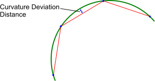
- Curvature Deviation Distance
- Maximum distance that is permitted between the center of any mesh edge and
its associated input surface. An illustration of this distance is shown
below:
Surface Growth Rate
This control determines the rate at which face edge sizes vary from one face to its neighbor. The effect is only seen when there is transition from an area of refinement to the rest of the surface mesh. For example, a value of 1.3 means that a face edge can be 1.3 times its neighbor length when growing from a short to a long edge length. The recommended range for Surface Growth Rate is 1.1 to 1.6.
This control is only available for the Surface Remesher.
Surface Growth Rate Properties
- Surface Growth Rate
- Specifies the maximum rate of face edge transition. Decreasing this value
generally produces a surface mesh with more faces.
- Default—computes a pre-determined
value based on the meshing method.
Meshing Method Default Value Triangle 1.3 Enhanced Quality Triangle 1.2 Quad Dominant 1.15 - Fast—generates large cells in a
pre-determined growth rate value that is based on the meshing
method. The surface growth rate value is printed in the output
log.
Meshing Method Example Triangle Surface growth rate value = 1.6. 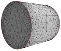
Enhanced Quality Triangle Surface growth rate value = 1.4. 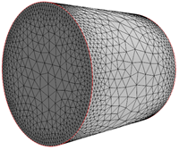
Quad Dominant Surface growth rate value = 1.3. 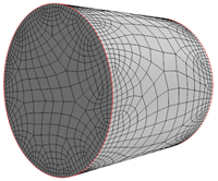
- Slow—generates small cells in a
pre-determined growth rate value that is based on the meshing
method. The value is printed in the output log.
Meshing Method Example Triangle Surface growth rate value = 1.1. 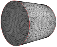
Enhanced Quality Triangle Surface growth rate value = 1.1. 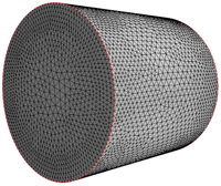
Quad Dominant Surface growth rate value = 1.05. 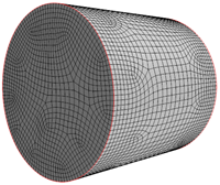
- User Specified —allows you to specify a value that overrides the default surface growth rate. You are recommended to use a surface growth rate in the range of 1.1 to 1.4 (Enhanced Quality Triangles) and 1.1 to 1.3 (Quad Dominant). Using a value outside the recommended range can result in a lower quality surface mesh.
- Default—computes a pre-determined
value based on the meshing method.
Surface Proximity
This control provides mesh refinement on surfaces that are closed to one another. The increased number of faces in the surface mesh produces more volume mesh cells between the gap.
Surface Proximity Properties
- # Points in a gap
- Determines the local face size by dividing the distance from one face to another across a gap by this value. However, if the gap distance is less than the Search Floor or more than the Search Ceiling, there is no refinement.
- Search Floor
- Specifies the minimum gap size that the mesher includes in proximity, which prevents unwanted refinement. This property is useful when the surface contains overlapping faces or faces that are too close, due to complex detail or CAD artifacts.
- Search Ceiling
- Specifies the maximum distance that the mesher includes in proximity, which prevents unwanted refinement. This property is useful if a component has a variable thickness and you need an option to locally refine only those areas where the thickness is less than a specified value.
- Search Direction
- Specifies the direction for surface proximity refinement. There are three
options for this:
- Inside—the surface proximity refinement is applied to surfaces inside of the selected part.
- Outside—the surface proximity refinement is applied to surfaces outside of the selected part.
- Both—the surface proximity refinement is applied to surfaces on either side of the selected part.
Target Surface Size
This value specifies the edge length that the mesher aims for in the absence of any mesh refinement. You can specify the target surface size as relative or absolute.
Decreasing the target surface size generates more refined and detailed surface mesh. However, this refinement increases the CPU time and size of the surface mesh.
Volume of Interest
This control determines the volume that the surface wrapper extracts from the original geometry surface.
Volume of Interest Properties
- Method
- There are four options for this:
- Largest Internal—specifies that the
wrapper extracts the largest internal, self-contained volume from
the input geometry surfaces. In the following example, the largest
internal volume is the red box, without the blue and green parts, as
internal geometries within the volume are maintained.

To ignore internal volumes that you do not want in the surface mesh, use the smallest wrapping volume control.
- External—the External method specifies that the surface wrapper
extracts the outer surfaces of all parts, that is, the external
surfaces. The following example demonstrates this method:
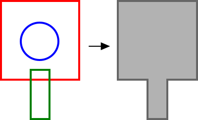
In this example, all internal surfaces are omitted from the final wrapped surface. If they are part of the outer surface, the intersecting surfaces are included to form one volume.
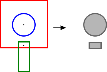
- Seed Point—specifies that a
user-defined location and coordinate system determines the surface
that the wrapper extracts. The resultant mesh is the surface that
surrounds this location. In this example, two seed points are placed
inside the blue and green volumes. The result from the wrapper is
two closed surfaces that are shown to the right of the diagram.
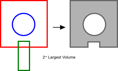
- Nth Largest —Specifies that the
wrapper extracts a particular surface according to volume size. The
surfaces are ranked from largest to smallest, and the user-defined
Volume Number determines the output surface. Geometries that
intersect one another are considered as both a single volume plus
individual volumes when assessing their volumetric size.The following example shows the second largest volume that is extracted from the input geometry, which is the red box minus all other parts.
To ignore internal volumes that you do not want in the surface mesh, use the smallest wrapping volume control.
- Largest Internal—specifies that the
wrapper extracts the largest internal, self-contained volume from
the input geometry surfaces. In the following example, the largest
internal volume is the red box, without the blue and green parts, as
internal geometries within the volume are maintained.