Injector Values Reference
This section describes the available injector values.
Depending on how the injector conditions are set, you can define injections using the following values:
- Aspect Ratio
- Axis
- Cone Randomization
- Cycle Time
- Fiber Length
- Fiber Radius
- Initial Overlap
- Injection Point Density
- Injector Axes
- Injector Diameter
- Injector Upstream Pressure
- Inner Cone Angle
- In-nozzle Nucleation
- Maximum Minor Axis Velocity
- Mean Injection Velocity
- Nozzle Baseline Contraction Coefficient
- Nozzle Discharge Coefficient
- Nozzle Diameter
- Nozzle Form Loss Coefficient
- Nozzle Inlet Roundness Ratio
- Nozzle Inlet Mass Flow Rate
- Nozzle Inlet Temperature
- Nozzle Length
- Nozzle Turbulence Dissipation Rate Coefficient
- Number of Fiber Segments
- Number of Seeds
- Outer Cone Angle
- Output Level Control
- Parcel Streams
- Particle Charge
- Particle Count
- Particle Orientation
- Particle Temperature
- Passive Scalar
- Point Inclusion Probability
- Polynomial Weighting
- Porosity limit
- Position
- Re-randomization
- Sheet Breakup Constant
- Spacing
- Swirl
- Swirl Angle
- Transfer Criterion
- Volume Flux
Aspect Ratio
Applies to: hollow cone and solid cone injectors when Cross Section Specification is set to Ellipse.
Specifies the ratio of the length of major axis to the length of minor axis. The default of 1.0 represents a circular cross section. This quantity must be greater than or equal to 1.
- Properties:
-
- Value
- A constant.
Axis
Applies to: nozzle injectors and to hollow cone or solid cone when the cone Cross Section Specification is set to Circle.
This value defines the central axis of the cone within which parcels are injected.
- Properties:
-
- Direction
- The direction of the axis. Specified as a vector in the chosen coordinate system.
- Origin
- The origin of the axis (and therefore the point from which parcels are injected). Specified as a position vector in the chosen coordinate system.
- Coordinate System
- The coordinate system in which the axis is defined. Select from a drop-down list of available systems.
Cone Randomization
Applies to: hollow cone or nozzle injectors in unsteady simulations.
This determines whether injection points change position randomly from time-step to time-step, or remain in fixed positions.
- Properties:
-
- Rerandomize
- When On, specifies that the injection points are randomized again for each time-step. When Off, re-uses the initial randomization. Off is the default.
- Value
- Proportion of the distance between initial positions over which injection points can vary between one time-step and the next, expressed as a value between 0 and 1. Effective only when Rerandomize is activated. The default value is 1.
Cycle Time
Applies to: the table injector when the Cyclic Injector Specification is on.
Specifies the length of time between injection cycles. Cycles repeat throughout the simulation.
Fiber Length
Applies to: the Flexible Fiber model.
Specifies the length of the cylindrical segments composing the flexible fiber model.
- Properties:
-
- Method
- Selects the method for specifying the length of the cylindrical segment. Common methods for a scalar profile can be used.
- Value
- The length of a cylindrical segment composing the flexible fiber model The default is 0.5 m.
- Dimensions
- Length. Read-only.
Fiber Radius
Applies to: the Flexible Fiber model.
Specifies the radius of the cylindrical segments composing the flexible fiber model.
- Properties:
-
- Method
- Selects the method for specifying the radius of the cylindrical segment. Common methods for a scalar profile can be used.
- Value
- The radius of a cylindrical segment composing the flexible fiber model. The default is 0.01 m.
- Dimensions
- Length. Read-only.
Initial Overlap
Applies to: the surface injector in DEM simulations when the Allow Overlap With Boundary injector condition is activated, or when the Project to Boundary condition is activated for the point, table or part injectors..
- Property
-
- Value
- Overlap with the boundary as a fraction of particle equivalent diameter (taken as the diameter of a sphere of equal volume). The value ranges between 0.0 and 0.49. The default is 0.01.
Injection Point Density
Applies to: the surface injector when the Random Injection injector condition is activated.
- Property
-
- Value
- Number of injection points per unit area of surface.
Injector Axes
Applies to: the hollow cone and solid cone injectors when the Cross Section Specification is set to Ellipse.
This value specifies the position and orientation of the elliptical cross section of a conical injector.
- Properties:
-
- Coordinate System
- The coordinate system in which the origin and the direction vectors of the axes of the injector are defined.
- Origin
- Origin of the axes of the injector (and therefore the point from which parcels are injected with respect to the coordinate system).
- Injector Axis
- Direction of the axis of the injector with respect to the coordinate system.
- Major Axis
- Direction of the major axis of the ellipse defining the cross section with respect to the coordinate system.
Injector Diameter
Applies to: the hollow cone injector when the Cross Section Specification is set to Circle.
This value defines the diameter of the injector hole through which the droplet fluid flows.
Injector Upstream Pressure
Applies to: the nozzle injector.
This value sets the upstream pressure, which is used to calculate in Eqn. (3061). Upstream pressure is the pressure head available to force liquid through the pressure swirl nozzle, and is used to predict the liquid sheet exit velocity.
Inner Cone Angle
Applies to: the hollow cone or nozzle injectors.
This value defines the internal angle of the cone about the central axis. A value of zero results in a solid cone formation.
In-nozzle Nucleation
Applies to: the Droplet Flash-Boiling model together with the nozzle injector, in implicit or PISO unsteady simulations.
Specifies parameters for flash boiling inside the nozzle.
- Properties:
-
- In-nozzle Degree of Superheat Threshold
- The level of superheat that is required to activate in-nozzle nucleation, in Eqn. (3126).
- Nucleation Density Exponent
- A model constant, in Eqn. (3135). The default value is 4.4.
- Departure Bubble Contact Angle
- The bubble-surface contact angle, in Eqn. (3133). The default value is 45.78 degrees.
Maximum Minor Axis Velocity
Applies to: the hollow cone and solid cone injectors when Cross Section Specification is set to Ellipse.
This value specifies the maximum velocity along the minor axis of the ellipse. The default is zero.
- Properties:
-
- Method
- Selects the method used for setting the value of the maximum velocity along the minor axis of the ellipse. Common profile methods can be used. If the Field Function method is selected, the field function can be defined as depending on other properties initialized during the injection of the particles.
- Value
- The maximum velocity along the minor axis of the ellipse. The defaults is 0.0 m/s.
- Dimensions
- The dimensionality of the velocity (read-only).
Mean Injection Velocity
Applies to: the Huh model together with the nozzle injector, in unsteady simulations.
Specifies in Eqn. (3080). The mean value is 1.0 m/s.
Minor Axis Length
Applies to: the hollow cone injector when Cross Section Specification is set to Ellipse.
Total length of the injector hole along the minor axis of the ellipse. The default is 0.
- Properties:
-
- Value
- A constant.
Nozzle Baseline Contraction Coefficient
Applies to: the Droplet Flash-Boiling model together with the nozzle injector, in implicit or PISO unsteady simulations.
A dimensionless constant inversely proportional to velocity at the vena contracta. Specifies in Eqn. (3128). The default value is 0.7.
Nozzle Discharge Coefficient
Applies to: the Huh model together with the nozzle injector, in unsteady simulations.
A dimensionless proportionality constant for the rate of volume flow through the nozzle. Specifies in Eqn. (3080). The default value is 0.6.
Nozzle Diameter
Applies to: the nozzle injector, in unsteady simulations.
The diameter of the circle through which parcels are injected. Specifies in Eqn. (3080). The default value is 3.0E-4.
Nozzle Form Loss Coefficient
Applies to: the Huh model together with the nozzle injector, in unsteady simulations.
A dimensionless proportionality constant for the pressure loss associated with the sharpness of the nozzle entrance corner. Specifies in Eqn. (3080). The default value is 0.45.
Nozzle Inlet Roundness Ratio
Applies to: the Droplet Flash-Boiling model together with the nozzle injector, in implicit or PISO unsteady simulations.
Specifies in Eqn. (3129). The default value is 0.07.
Nozzle Inlet Mass Flow Rate
Applies to: the Droplet Flash-Boiling model together with the nozzle injector, in implicit or PISO unsteady simulations.
Specifies in Eqn. (3127).
Nozzle Inlet Temperature
Applies to: the Droplet Flash-Boiling model together with the nozzle injector, in implicit or PISO unsteady simulations.
Specifies in Eqn. (3125). The default value is 333 K.
Nozzle Length
Applies to: the Huh model together with the nozzle injector, in unsteady simulations.
The length of the channel through the nozzle. Specifies in Eqn. (3080). The default value is 0.0012 m.
Nozzle Turbulence Dissipation Rate Coefficient
Applies to: the Huh model together with the nozzle injector, in unsteady simulations.
Specifies in Eqn. (3080). The default value is 0.5.
Number of Fiber Segments
Applies to: the Flexible Fiber model.
Specifies the number of cylindrical segments in the flexible fiber model.
- Property:
-
- Value
- The number of cylindrical segments in the flexible fiber model. The default value is 3.
Number of Seeds
Applies to: the random injector.
The number of particles the random injector tries to inject at the same time. See the Injector Conditions Reference.
- Property:
-
- Value
- Number of seeds used to generate injection points. The value can be set as an expression that evaluates to a spatially invariant constant. The value can be time dependent. The default value is 100.
Outer Cone Angle
Applies to: the hollow cone, solid cone, or nozzle injectors.
This value defines the outer angle of the cone about the central axis, within which parcels are injected.
Output Level Control
Applies to: the Huh model together with the nozzle injector.
- Property:
-
- Verbose
- When On, displays half-cone angle in the output window. Off is the default.
Parcel Streams
This value sets the number of parcel streams per injection point (and per time-step in unsteady simulations). This quantity has no influence on the mass or volume flow rate from the injector, but instead can influence accuracy, depending on other selections. Specifically:
- With the Turbulent Dispersion model, increasing the number of parcel streams increases accuracy by creating a larger ensemble of tracks from each injection point, each representing a different realization of the particle trajectory. Typically 10–100 parcel streams are specified for this purpose.
- With particle size distributions on film stripping injectors, increasing the number of parcel streams improves the resolution of the particle size distribution. Typically 5–20 parcel streams are specified for this purpose. The particle size distributions for part, surface, and table injectors are sampled at each injection point, so usually 1–5 parcel streams represent the distribution well, depending on the number of injection points located on the surface.
The combined effect of both of the above, is multiplicative. If neither is relevant, use the default number of parcel streams (1). CPU time is directly proportional to this quantity.
- Properties:
-
- Value
-
- In steady simulations, the number of parcel tracks originating from each injection point.
- In unsteady simulations, the number of parcels introduced at each injection point at the start of each time-step.
The number of parcel streams can be a constant or derived from an expression. Expressions allow the value to vary with time or other conditions. Field functions are allowed.
All values, whether from expressions or constants, are rounded to the nearest integer. Values lower than 1 generate an error.
Particle Charge
Applies to: the Coulomb Force model.
This value is entered as a scalar profile. If the Field Function method is selected, the field function can be defined as depending on other properties initialized during the injection of the particles.
Particle Count
Applies to: the table injectors or random injector.
Added to the tree under one of two conditions:
- When Injector Type is set to Table Injector and Table Type is set to Parcels Table.
- When Injector Type is set to Random Injector and the Particle Packing Specification is set to Particle Count.
Particle Orientation
Applies to: non-spherical DEM particle shapes.
Used to specify the initial orientation of the particle as it is injected.
- Properties:
-
- Method
- Selects the method for entering the particle orientation:
- Constant
- Field Function
- Normally distributed
- Table (iteration)
- Table (time)
- Uniformly distributed
- Injection Table
- Value
- Specifies the and values. These values are separated by commas in a text entry. You can also enter an expression, such as 10 * sin(3.14 * $Time), directly. The property customizer opens a dialog which contains separate fields for these values. This property is only available when Method is set to Constant.
- Angles Function
- Activates an object selector dialog from which you can choose a field function. This property is only available when Method is set to Field Function.
- Dimensions
- The dimensionality of the particle orientation (read-only).
Particle Temperature
Applies to: the Lagrangian Energy model.
This value is entered as a scalar profile. If the Field Function method is selected, the field function can be defined as depending on other properties initialized during the injection of the particles.
Passive Scalar
Applies to: the Passive Scalar model.
- Properties:
-
- Method
- Selects the method used for setting the value of the scalar on
the particle as the particle enters the simulation.
- Constant
- Set the values of all individual scalars as a vector of constants.
- Composite
- Set the value of each passive scalar separately (constant, field function, table or user code). If you use a table injector, individual passive scalars can be initialized by an injection table. Individual passive scalars can be described with field functions, which can be defined as depending on other properties initialized during the injection of the particles.
- Injection Table
- Set the value of the passive scalar for each component according to an injection table. The table specifies the location of injection points, the time of injection, and the passive scalar value of each component separately. Used only with table injectors.
- Dimensions
- The dimensionality of the value, Mass/Volume-Time (read-only). The passive scalar itself is always dimensionless, but its source term has units referring to the density of the receiving phase over time.
Point Inclusion Probability
Applies to: the part injector.
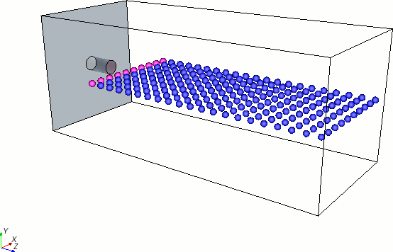
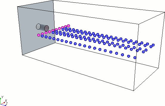
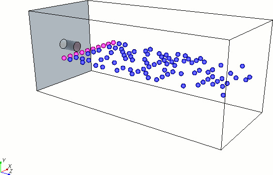
This node sets the probability of a point being included in the set of points from which particles are injected. In the example that is shown below, a line probe derived part with a resolution of 11 is used as the input part for the injector. This configuration means that 10 points are available from which to inject particles. In the first screenshot, the point inclusion probability is set to 1.0, which means that the injector uses all points that are extracted from the part. In the second screenshot, the point inclusion probability is set to 0.4, meaning that only a subset of the points is used. In the third screenshot, the Re-randomize property is activated, regenerating the injection points at the start of each time-step.
- Point Inclusion Probability = 1.0

- Point Inclusion Probability = 0.4

- Point Inclusion Probability = 0.4, with re-randomizing option
activated

- Properties:
-
- Value
- The probability that a point in the injector is used as an injection point. The probability is applied to each part point.
- Re-randomize
- When On, regenerates the injection points at the start of each time-step. When Off, leaves injection points fixed after the start of the simulation (as in a steady analysis). Available for transient analyses only.
Polyhedron Elongation Factor
Applies to: the Polyhedral Particles model.
- Properties:
-
- Method
- Selects the method for specifying the dimensions of polyhedral particles. Common methods for a scalar profile can be used.
- Value
- An ordered triplet of multipliers for the length of the polyhedron along three axes of the particle's principal moment of inertia, enabling the injection of polyhedra of varying proportion, based on the template described in the Part property of the Polyhedral Particle model. The default is [1.0, 1.0, 1.0] for no change. Use values greater than one to elongate along an axis, or less than one to shrink.
- Dimensions
- The units for the size of the template particle. Read-only.
- Coordinate System
- The coordinate system in which the template particle is defined. Select from a drop-down list of available systems.
Polynomial Weighting
Applies to: the solid cone and hollow cone injectors.
By default, when the Cone Angle Sample Distribution condition is Off, the parcel streams are sampled such that the surface of the cone (after a time ) is uniform as a function of and in a spherical coordinate system with the injection point as the origin.
When the condition is On, the injection in is weighted so that the sample density is biased along the injection direction.
where:
-
and
are the inner and outer cone angles. See Hollow Cone Injector.
- For a solid cone, .
- For weighting functions with the form of , values of has a higher sample density at the centerline of the spray.
- is an angle ranging from 0 to 1. For a uniform distribution, .
When the weighted distribution
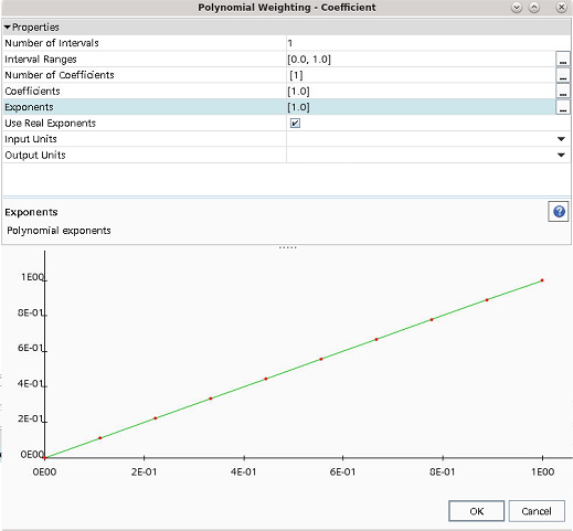
condition is On, define the polynomial coefficient by selecting the editor
 of the Coefficient propery of the Polynomial
Weighting node then specifying the following variables:
- Properties:
-
- Number of Intervals
- Sets the number of intervals that define the curve of the coefficient polynomial. You can specify different equations for each interval of the curve.
- Interval Ranges
- Specifies the
minimum and maximum values of each interval.
For example, to specify three intervals [A, B], [B, C], [C, D], you enter [A, B, C, D].
- Number of Coefficients
- Specifies the
number of coefficients per interval.
For example, to specify the coefficients for the intervals [A, B], [B, C], [C, D], you enter [a, b, c]. In this example, a is the number of coefficients for interval [A, B], b is the number for interval [B, C], and c is the number for interval [C, D].
- Coefficients
- Specifies the
coefficients for each of the terms in the polynomial equation.
You enter the values for each interval, in order.
For example, if a=3, b=2, and c=4, enter the values in the format: [a1, a2, a3, b1, b2, c1, c2, c3, c4].
- Exponents
- Specifies the exponents for each of the terms in the polynomial equation. You enter the values for each interval in order, in the same format as for the coefficients.
- Use Real Exponents
-
Controls how polynomials are calculated.
- Input Units
- Specifies the units for the input variable (the X-axis) of the polynomial equation.
- Output Units
- Specifies the units for the output variable (the Y-axis) of the polynomial equation.

Porosity limit
Applies to: the random injector.
The maximum packing limit for particles that are introduced into the injected region. See the Injector Conditions Reference.
- Property:
-
- Value
- The maximum packing limit. The value can be set as an expression that evaluates to a spatially invariant constant. The value can be time dependent. The default value is 0.1.
Position
Applies to: the point injector.
- Properties:
-
- Coordinate System
- The coordinate system in which the position is defined. Select from a drop-down list of available systems.
- Value
- The value and units of the position. Clicking the customizer executes the define value action. An expression is not accepted for this entry.
Re-randomization
Applies to: the surface injector when the Random Injection injector condition is activated.
When On, specifies that the injection points are randomized again for each time-step. When Off, re-uses the initial randomization. Off is the default.
Sheet Breakup Constant
Applies to: the nozzle injector with the LISA model.
This value is an empirical constant, in Eqn. (3068), that calibrates the ratio of the sheet surface disturbance at breakup to its initial value in the dispersion relation of the LISA model. It is set to 12 by default.
Spacing
Applies to: the lattice injector.
This value allows you to control the dimensions of the bounding box in the x, y, and z directions. Clicking the customizer executes the define value action. An expression is not accepted for this entry.
Species Mass Fraction
Applies to: the Species model.
This value allows you to control the mass fractions of multi-component particles and droplets using common properties of a scalar profile.
Swirl
Applies to: the hollow cone injector.
This value defines additional angular velocity about the axis, added to existing velocity. It is set to zero by default.
Swirl Angle
Applies to: the nozzle injector with the LISA model.
This value defines the angular/azimuthal velocity component about the injector axis of the atomized droplets. It is set to zero by default.
Transfer Criterion
Applies to: the parcel transfer injector.
The criterion is entered as an
expression in the Custom Editor ( ).
).
If the transfer criterion for a parcel in the source phase evaluates as non-zero, the parcel is transferred to the destination phase.
Volume Flux
Applies to: the surface injector.
Added to the tree when Volume Flux is chosen as the Flow Rate Specification. It is entered as a scalar profile. The actual volume flow rate through each individual face of the injector surface is the product of the face surface area and the specified volume flux.