Understanding Injector Types
Each type of injector has distinctive features that determine where and how particles are injected.
The following injector types are provided in Simcenter STAR-CCM+:
- Part injector
- Point injector
- Hollow Cone injector
- Solid Cone injector
- Surface injector
- Nozzle injector
- Table injector
- Parcel Transfer injector
- Lattice injector—used with the Discrete Element Method (DEM)
- Random injector—used with the Discrete Element Method (DEM)
- Film Stripping injector—used with the Fluid Film model
- Volume Stripping injector—used with the VOF-Lagrangian User Stripping or Resolved VOF-Lagrangian Transition model.
Each type has distinctive features that determine where and how particles are injected. A common property among all injector types is the injector Inputs property. As its use varies between injector types, it is important to understand how the property is used in each injector: this property is discussed in the individual descriptions below. The type of the injector can also collaborate with the Lagrangian phase models to determine which conditions and values are necessary to define the initial conditions completely.
A key role of the type of injector is to determine how the injection points are generated from the Inputs of the injector. Injection points are where the injector introduces particles—in other words the initial positions of the particles.
Part Injector
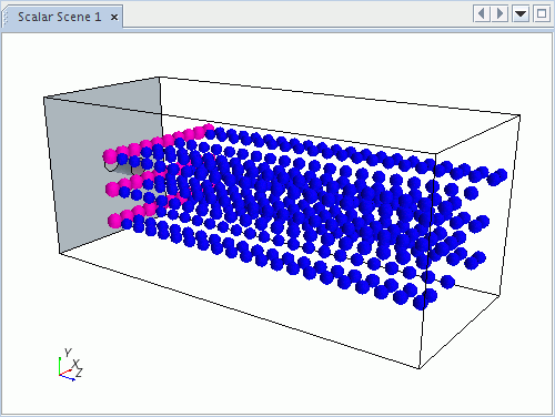
A part injector represents a collection of injection points that are extracted from the geometry of the parts of the injector. If desired, the points can be a subset of the points that are defined on the parts. The point inclusion probability property of the injector sets the probability that a particular point is used. An example of a part injector (defined by three line probes) is shown below.
Point Injector
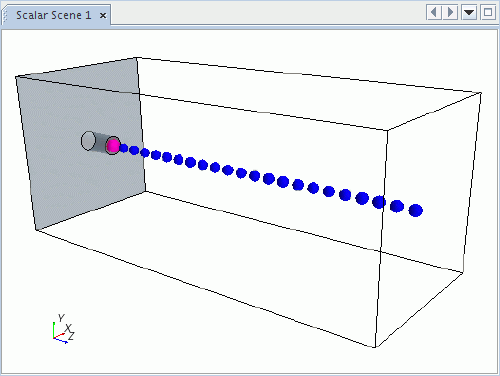
A point injector injects at a single user-specified point which is the position of the injector. The initial cell location for this point is found by searching the parts of the injector, which are limited to regions. Thus, if you can specify which region contains the point, the input parts can be used to accelerate the cell location process. You can also use input parts to resolve ambiguities. For example, suppose that the point lies on the interface between two regions but the intention is not to inject into one of them. An error is thrown if a cell location for the point injector cannot be found by searching its input parts. Typically this error means that the point is outside the specified region or regions.
Hollow Cone Injector
A hollow cone injector injects parcels in a cone formation about an axis you specify. An injector diameter, an inner cone angle, and an outer cone angle define the cone, as shown in the diagram below. (The diagram shows only half the cone; the injector uses a whole cone. The example shown has an injector diameter of zero.)
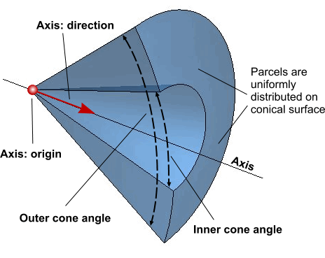
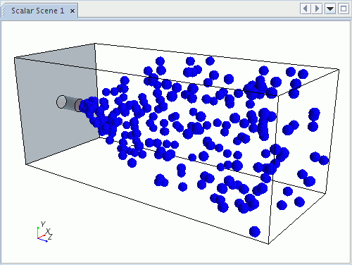
The specified number of parcel streams are injected in random directions conforming to a uniform distribution on the surface of the cone. Given the direction, the velocity is obtained using the specified velocity magnitude. In steady simulations, each iteration uses the same stochastically chosen direction and size distribution. In unsteady simulations, the direction and size distribution are randomized again and newly sampled each time-step, if you activate the Cone Randomization property. For this injector, the Inputs property is used to define the region within which the origin of the axis is located.
Solid Cone Injector
A solid cone injector is similar to the hollow cone type, except that there is no inner cone angle parameter (the angle is treated as zero).
Surface Injector
A surface injector injects parcels of any Lagrangian phase from each face of the surface comprising the parts of the injector. By default, injection points are the centroids of each face. The surface injector can also use the random injection condition. For this injector type, injected parts are selected from those parts that belong to the model geometry.
A unique feature of the surface injector type is that the injection flow rate can be defined with a flux, that is, as a rate per unit area. The final flow rate is the product of the face area and the specified flux, whether this flux is a particle, mass or volume flux. In the following example, the initial location of each parcel coincides with the centroid of each face on the starting surface. The mass of each parcel is proportional to the area of the face from which it came (as a mass flux has been specified).
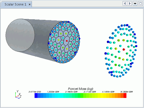
When the flow rate through a surface injector is defined directly, the flow rate through each face scales to the ratio of the face area to the overall surface area.
Nozzle Injector
A nozzle injector requires two basic parameters: the diameter of the injector at the nozzle exit and the origin and axis of the injector. The nozzle injector becomes available only if you choose of the primary atomization models, LISA or Huh. Additional model-specific parameters are then added, based on the selected model.
When used with the LISA Atomization model, this injector type represents a pressure-swirl atomizer. A thin liquid film is formed within the injector nozzle that then breaks up into droplets soon after entering the gas. A mathematical model represents the breakup process. This model derives from a stability analysis of the two-dimensional liquid film.
For this injector type, the Inputs property is used to define the region where the origin of the axis is located. The inner cone angle and outer cone angle are used to calculate the spray angle, which is defined as half the sum of the inner and outer cone angles. The model also requires an injector upstream pressure value to predict the exit velocity of the thin liquid film.
When used with the Huh atomization model, this injector represents a liquid jet breaking up into droplets as it enters the gas. The initial droplets have diameters equal to the nozzle diameter, then break up according to the Huh model.
Since Huh model estimates the initial turbulence-generated perturbations from an analysis of the flow through the nozzle, it requires additional nozzle-related parameters, as outlined in the formulation (see Huh Model).
| 注 | Only parcels injected from a nozzle injector can go through primary atomization. Parcels from other types of injector skip the primary atomization process. |
When used with the Droplet Flash-Boiling model, this injector models the cavitation and nucleation processes inside the injector nozzle. Droplet velocity, size, and temperature at the nozzle exit depend on the parameters of the nozzle, as described in In-Nozzle Nucleation.
The nozzle injector can inject continuous fluid phase and Lagrangian parcels simultaneously.
These injectors are only available for use with the three-dimensional space model.
Table Injector
A table injector injects parcels from points that are specified in an input table. The table also specifies the injection times and the properties of the parcels, such as mass, diameter, and temperature.
Input parts for a table injector must be regions. The injection points can be anywhere within a specified region.
Parcel Transfer Injector
The Parcel Transfer injector replaces parcels of a selected input phase with parcels of a selected output phase. There are two types of parcel transfer:
- For parcel transfers from DEM to DEM phase, Lagrangian free-stream to another
Lagrangian free-stream phase, or DEM to Lagrangian free-stream phase, a transfer
criterion must be specified to initiate the phase conversion.
Input and output phases can be either free-stream Lagrangian parcels or DEM parcels (particles). However, the combination of Lagrangian input and DEM output is not allowed. Input and output particles must be spherical, isothermal, and of a single component. The transfer preserves the total mass and velocity (and therefore total momentum and kinetic energy). Input and output particles have the same injector index.
The Transfer Criterion value node controls which parcels in the source phase the injector reinjects into the destination phase. Click (Custom Editor) and enter the criterion in the dialog window, either directly or selecting system functions from the Reference tab in the Transfer Criterion dialog. Example:
$ParticleDiameter < 0.05This criterion transfers particles in the source phase with a diameter below 0.05 m. If you create more than one Parcel Transfer injector, the injectors act in order of their Index numbers. First, injector 1 reinjects all DEM particles that meet criterion 1, then injector 2 reinjects the remaining DEM particles meeting criterion 2, and so on.
Example: If particles modeled with DEM become smaller through breakup or reaction, or move into a region with large cells, the particles are then small compared to the distances between them. Collisions between particles then become insignificant. In such a case, non-DEM Lagrangian parcels can be a better model. You can use the Parcel Transfer injector to reinject the DEM particles as Lagrangian parcels, at the same position.
- For transfers from a Lagrangian free-stream phase to a Lagrangian wall-bound phase, the specification of a transfer criterion is not required. As soon as a free-stream phase interacts with a wall boundary, the transition to wall-bound phase takes place. Therefore, the transfer condition method is set to Model Driven. In this case, the input phase must be Lagrangian free-stream and the output phase must be Lagrangian wall-bound. For this type of transfer, mass, energy, and tangential momentum are conserved.
The Parcel Transfer injector is incompatible with the Passive Scalar model.
Volume Stripping Injector
A volume stripping injector injects parcels from a Eulerian volume fraction field by User VOF-Lagrangian Stripping or Resolved VOF-Lagrangian Transition models.
The Lagrangian phase for a volume stripping injector must be liquid, multi-component liquid, gas, or multi-component gas material particles. Input parts for a volume stripping injector must be fluid regions. The injection points are evaluated within the specified regions.