Adjusting the Interface Settings (Topology-Based Method)
When the direct intersector is set to the topology-based Method, Simcenter STAR-CCM+ computes the intersection of interface boundaries using an algorithm that identifies large scale topological features.
- match outer boundary flag
- projection tolerance
- angle threshold
The topology-based method is multi-threaded, which allows parallel computation. Compared to the default geometry-based (Legacy) method, the topology-based method is faster and results in higher quality intersections. It also provides the ability to close adjacent cells.
The topology-based algorithm requires that the input meshes are 2-manifolds (orientable surfaces). The parent surfaces cannot contain X or T junctions. When the intersection is successful, this requirement improves the solution accuracy, and often results in a smaller maximum skewness angle on cells touching the interface.
Unsuccessful intersections can manifest in different ways, such as inverted cells with negative volumes, or an unexpectedly high number of remainder (unintersected) faces.
Before you start adjusting the interface settings, find the exact locations of the inverted cells. For interfaces updated through mesh motion, check whether the inverted cells remain at the same locations during motion.
- Select the Interfaces node and set Direct Intersector to Topology-Based.
If cells are finer on one side of the interface, they may represent the surface of intersection more accurately. In this case, you can choose the finer side as the fixed side. To swap the fixed and adapted interface sides, reverse the orientation of the interface:.
- To reverse the orientation, right-click the node and select Reverse Orientation.
- Select the node and set the intersection properties.Depending on the connectivity of the topology-based interface, set the following properties:
Intersector Connectivity Adjustment Topology-Based Imprinted -
Match Outer
Boundary: Indicates that the
interface boundaries are expected to fully overlap on
large-scale topological features. Activate this option only
when you expect a complete match of the two boundaries of an
interface. By default, this property is deactivated.
- Activate Match Outer Boundary if you expect a complete match between two non-closed parent surfaces.
- Deactivate Match Outer Boundary if two non-closed parent surfaces partially overlap.
- Match Outer Boundary has no influence for matching two closed parent surfaces.
- Projection Tolerance: Specifies the maximum orthogonal projection distance in terms of a fraction of local element diameter. Places a limit on how the vertices of the adapted side get projected onto the fixed side. In cases where the two interface boundaries are separated by greater distances, you can increase the Projection Tolerance value to get fewer remainder faces. By default, the tolerance is set to 0.2.
- Angle Threshold: Specifies the maximum angle (deg) by which the intersector identifies large-scale features that are mapped from the adapted side onto the fixed side. To preserve sharper features, specify a smaller Angle Threshold value. If the boundary meshes have spurious defects, you can specify a larger value. By default, the value is set to 45 deg.
Topology-Based Conformal The conformal connectivity type only applies to finite element models.
- Conformal Tolerance: Detects conformal faces in terms of a fraction of local element diameter. If too many conformal faces are matched, you can lower the value. If too few, you can increase it. By default, the value is 0.01.
- Nonconformal Tolerance: Detects non-conformal faces in terms of a fraction of local element diameter. If too many non-conformal faces are matched, you can lower the value. If too few, you can increase it. By default, the value is 0.01.
The following example shows a case where activating Match Outer Boundary helps to eliminate remainder faces. In this setup there is a rotating cylinder with 3 separate contacts: top, bottom, and sides.
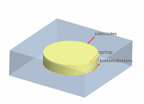
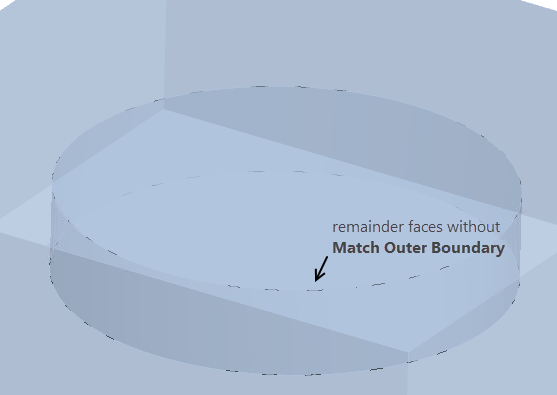
When Match Outer Boundary is deactivated, the topology-based intersector returns remainder (unintersected) faces near the shared edges between the side of the cylinder and the top (bottom) of the cylinder.
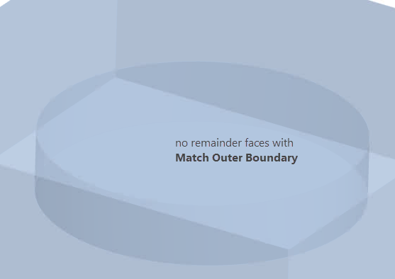
When you require a complete match, activate Match Outer Boundary. When activated, the topology-based intersector gives 0 remainder faces.
注 A similar setup with a single contact for the entire cylinder (instead of 3 separate contacts) provides a closed surface. In this case, the topology-based intersector gives no remainder faces, and activating the match outer boundary is not necessary. -
Match Outer
Boundary: Indicates that the
interface boundaries are expected to fully overlap on
large-scale topological features. Activate this option only
when you expect a complete match of the two boundaries of an
interface. By default, this property is deactivated.
- Select the node and activate the following properties:
- Allow Per-Contact Values—allows you to use different tolerances for each contact.
- Close Adjacent Cells— modifies cell connectivity between the interface faces and
side faces along common edges. A comparison of the topology-based
interface matching with and without Close
Adjacent Cells is shown below:
Topology-Based Intersection with Close Adjacent Cells Topology-Based Intersection without Close Adjacent Cells 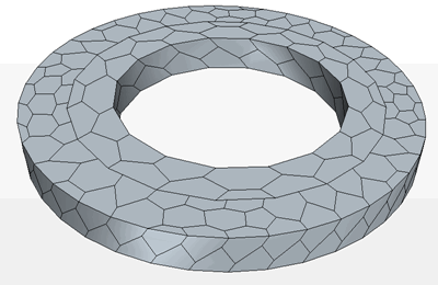
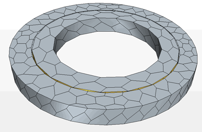
Guidelines for Close Adjacent Cells:- Use only one interface to define each disjoint closed-cell rotating cylinder interface.
- When Close Adjacent Cells is activated, define each closed-cell interface with a single part surface contact, instead of multiple part surface contacts per interface to improve performance.
- Only activate Close Adjacent Cells when required since the extra work makes the topology-based intersector slower.
- Use fewer prism layers near closed-cell interfaces since cells with a very thin aspect ratio near the interface can lead to negative volume cells.
- Activating Close Adjacent Cells does not help to reduce the negative cells which are already generated during interface intersection process.
- Do not use cells that are thinner than any
potential gap that will be filled between the two interface
sides. This causes negative volumes.
注 Close Adjacent Cells is not compatible with DFBI Motion.
- Reset on Relative Motion—Read Only for topology-based intersector. Simcenter STAR-CCM+ resets and reinitializes the interface at each time-step when it detects relative motion between the two parent faces. No interface update occurs in case of no relative motion.