Adjusting the Interface Settings (Metrics-Based Method)
For sliding-interface applications, Simcenter STAR-CCM+ provides the metrics-based intersector. This intersector requires a relative motion between the two sides of the interface.
When applying the metrics-based intersector, Simcenter STAR-CCM+ computes the intersection of interface boundaries using metrical faces. These faces contain no vertex informations, but only two parent faces, one area vector, and one centroid vector. This algorithm enables a fast computation of the interface intersection, but has implications for post-processing options (see Post-Processing Considerations with Metrics-Based Interfaces). The implementation is multi-threaded.
The following models are currently not compatible with the metrics-based intersector:
- Axisymmetric Model
- Battery Model
- Finite Element Models—Finite Element Solid Energy, Solid Stress, Finite Element Magnetic Vector Potential, Viscous Flow
- Fluid Film Model
- Lagrangian Model
- MidSideVertex Model
- Partitioned Coupling Model
- Adjoint Model
- Ensure that you have defined a relative motion between two sides of the proposed metrics-based interface. To check, select the node of both related regions and identify different motions/reference frames.
-
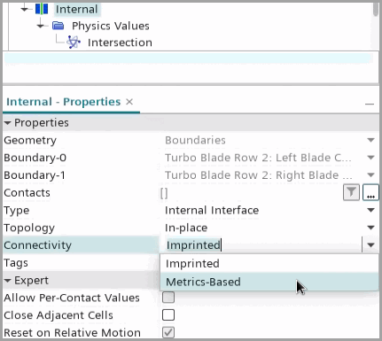
Select the node and set Connectivity to Metrics-Based.
This option is only available when the Type is Internal Interface with the Topology In-place.

-
Select the node and set the intersection properties.
To set properties mentioned above (except Match Feature Curves), refer to the example in Adjusting the Interface Settings (Topology-Based Method). The topology-based method and the metrics-based method share many geometric parameters in their coupling algorithms.
Property Value Match Outer Boundary Indicates that the interface boundaries are expected to fully overlap on large-scale topological features. Activate this option only when you expect a complete match of the two boundaries of an interface. By default, this property is deactivated. Guidelines for setting this property are as follows:
- Activate Match Outer Boundary if you expect a complete match between two non-closed parent surfaces.
- Deactivate Match Outer Boundary if two non-closed parent surfaces partially overlap.
- Match Outer Boundary has no influence for matching two closed parent surfaces.
Match Feature Curves Indicates that meshes have edge features that match up along feature curves. This option can help to reduce remainder faces. The default value is true. Projection Tolerance Specifies the maximum orthogonal projection distance in terms of a fraction of local element diameter. Places a limit on how the vertices of the adapted side get projected onto the fixed side. In cases where the two interface boundaries are separated by greater distances, you can increase the Projection Tolerance value to get fewer remainder faces. By default, the tolerance is set to 0.2. Angle Threshold Specifies the maximum angle (deg) by which the intersector identifies large-scale features that are mapped from the adapted side onto the fixed side. To preserve sharper features, specify a smaller Angle Threshold value. If the boundary meshes have spurious defects, you can specify a larger value. By default, the value is set to 45 deg.
Guidelines for the metrics-based method:
- Topologically, a metrics-based interface should not share boundaries (or part surfaces for contact-mode interfaces) with non-metrics-based interfaces.
- Due to computational performance, a metrics-based interface should not share boundaries (or part surfaces) with another metrics-based interface. Sharing boundaries serializes the intersection computation and results in a lower performance.
- In cases where sharing boundaries or part surfaces can not be
avoided, a fixed side Boundary-0 can match multiple adapted sides, but not
vice versa.
The two interface boundaries are called Boundary-0 and Boundary-1. Boundary-0 is the fixed side, onto which the vertices from the adapted side Boundary-1 are projected.