Intersecting an Interface
The intersection process occurs the first time the solution is initialized for the volume mesh.
This process involves the appropriate mesh calculations required to define the interface fully. For large problems with complex physics, it is generally advantageous (especially with regard to memory usage) to check the interface intersection after activating the Space model but before activating other models.
Intersection populates the interface boundary nodes with pieces of faces of the original boundaries. The faces belonging to the original boundary are removed. For a perfect intersection, where the matching areas of the original boundaries are the same, then the boundaries are left with zero faces. The boundary nodes however are not removed as the intersection process is reversible.
If the intersection process is not perfect or if the overlapping areas of the original boundaries are different, then there are some faces remaining in the original boundary nodes. Depending on the situation, examine these left over faces. If they are acceptable, then assign the appropriate boundary types and conditions to them. If they are not acceptable then the intersecting tolerance can be changed and the interface reset before trying the intersecting process again.
Once the interfaces have been created or reset, the intersection process can be performed in one of two ways:
- by manually initializing the solution
- by using the manager node
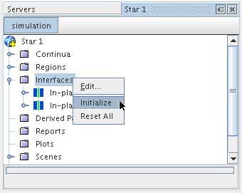
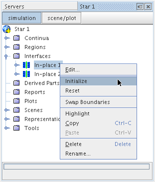
In the case of repeating interfaces used for sliding mesh calculations, the reintersection is done dynamically.

If the match between the two boundaries is conformal (that is, the primary and secondary boundary faces are all aligned and no additional intersections are required to produce a one-to-one connection) then this is indicated as such in the output, as shown above. If intersection of faces is required then the % difference in face area between the primary and secondary boundaries are shown instead. If the boundary perimeters are similar then only a small difference in intersection area is expected.
Additional information can be displayed in the output window by changing the interface verbosity.
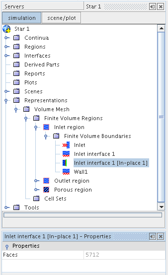
The interface boundary node is active.
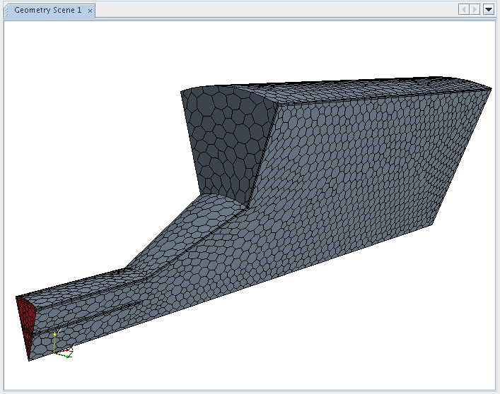
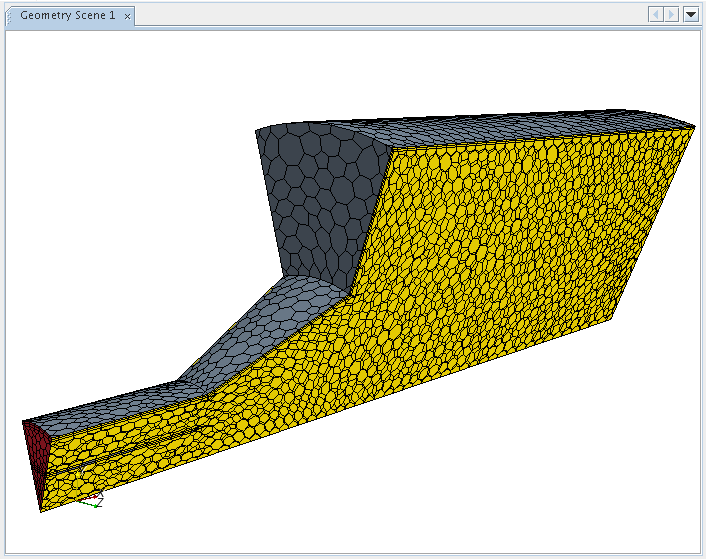
The intersection process increases the number of faces that exist at the boundaries making up the interface. This is due to the process of subdividing the boundaries on each side so that a conformal, one-to-one connection is formed between each face making up the interface. An example before and after illustration showing the interface intersections on a periodic interface is shown below:
 |
|
 |