Interfaces Overview
Interfaces are used in Simcenter STAR-CCM+ to transfer solution quantities between regions in a simulation. Certain types of interfaces modify quantities passing across them, such as a porous baffle interface that presents resistance to fluid flow. Periodic and repeating interfaces allow you to reduce the scope of the solution domain.
Mass, momentum, energy, or any other simulation quantity cannot pass from one region to another unless an interface is in place between them.
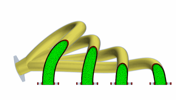
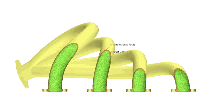
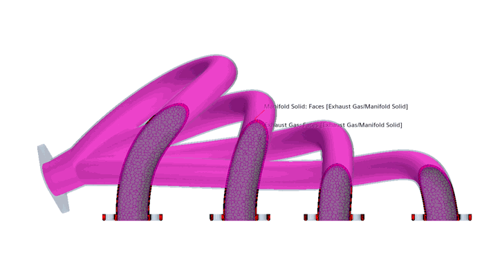
As shown below, a contact interface (yellow) is present between the solid region (red) and fluid region (green) so that the heat flux can pass between them.

Simcenter STAR-CCM+ provides the following categories of interface:
- Boundary-Mode Boundary Interfaces
- These interfaces are formed between a pair of boundaries that belong to either the same region or different regions. Only one pair of boundaries can be allocated to an interface. This restriction means that simulations with a high number of adjacent regions require a high number of interfaces, which can be difficult to manage.
- Contact-Mode Boundary Interfaces
- For regions that are constructed from one or more geometry parts, this type of interface allows you to define connections based on part contacts defined within the Geometry node. There is no restriction on the number of part contacts that you can allocate to a contact-mode boundary interface. For example, you can have one region that contains all the parts that represent electronic components on a motherboard. This region would have two interfaces: one for the connection between the components and the air, and another for connections between the components themselves.
- Region Interfaces
- Region to region interfaces
operate on all cells within the connected regions, rather than adjoining
surfaces. The two types of region-based interface are:
- Overset: these interfaces facilitate overlapping meshes
- Heat exchanger: this interface type is for simulating heat transfer between cold and hot fluids in a heat exchanger
Interfaces Properties
You can access all interfaces that are created during the simulation setup process via the Interfaces manager node.

The properties you specify in the Interfaces manager node apply to all the interfaces.
- Verbosity
- Controls the level of detail output at the interface initialization. When the option is enabled, more detail is printed to the output window.
- Contact Selection Priority
- Lets you prioritize the assignment of contacts when assigning them with a dynamic query. See Prioritizing Assignment of Parts.
- Interfaces
- The number of interfaces that are created in the simulation (Read Only).
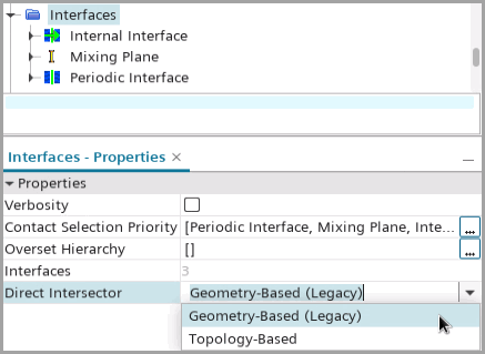
- Direct Intersector
- Specifies the method that Simcenter STAR-CCM+ uses to initialize
direct interfaces (that is, interfaces not with
Indirect connecitivity. It could be with
Imprinted, Conformal or
Metrics-Based connectivity). The available
options are:
- Geometry-Based (Legacy): default option. Simcenter STAR-CCM+ computes the intersection of interface boundaries using a geometry-based algorithm. This algorithm uses a single parameter based on a fraction of the minimum edge length around each vertex.
- Topology-Based: Simcenter STAR-CCM+ computes the intersection of interface boundaries using a topology-based algorithm. This algorithm identifies large-scale topological features based on detecting conformal and non-conformal faces.
The selected option, together with the connectivity type of each individual interface, determines the properties available for the node, which is a physics value node available for all direct interfaces. In the connectivity type, you can activate the third type of direct intersector—Metrics-Based. When the Metrics-Based connectivity type is activated, it overwrites the direct intersector specification in the Interfaces node.
Interfaces Right-Click Options
The following pop-up menu items available when you right-click the manager node:
- Initialize
- Populates the interface boundary nodes with faces from the original boundaries for all child interfaces.
- Reset All
- Removes initialization from all child interfaces. Any vertices that are removed are reported in the output window for each region.
- New Group
- Facilitates the grouping of objects by creating a group node within the manager node. Interface nodes can then be dragged and dropped into the new sub-folder.
- Group By
- Facilitates the grouping of objects by moving interfaces with common properties into a property category selected in the sub-menu. If you then change the property for a given interface node then it does not automatically move to the appropriate sub-folder.
- Ungroup
- Reverses the grouping process.
Interface Highlighting
Clicking on interfaces under the Interfaces node highlights the associated interfaces in the Graphics window.


Computation of Values on Interfaces
When you define a profile on an interface using a field function, Simcenter STAR-CCM+ evaluates the field function twice (once on each interface boundary) and then averages the result.
It can be that a function that is required by the field function does not exist on both sides of the interface, in which case an error message is generated. To avoid this problem, use the alternateValue function in the field function definition to provide a value when one cannot otherwise be found.
For example, a scalar profile that is defined as alternateValue($Pressure, 100000) is evaluated as 0.5*($Pressure + 100000) when $Pressure is only available on one side of the interface.
Asymmetric Values on Interface Boundaries
In some scenarios, the information that is held on the two boundaries of an interface is not the same. Depending on the type of interface, the symmetry of data that is available for input can be broken. The asymmetric interface values are as follows:
- Porous Baffle Velocity Specification
- For a Resistance Based porous baffle, the flow velocity is the same on both sides of the baffle. The flow profile is specified on the upstream side of the baffle (Boundary-0) only. The flow profile on the downstream side (Boundary-1) is computed from the values on Boundary-0 by using an appropriate transformation.