Generating the Surface and Volume Mesh
Meshing parts generates the surface and volume discretization of the imported CAD geometry. The solvers use this discretization to obtain a physical solution.
To Generate Surface and Volume Mesh:
- Right-click the node and select .
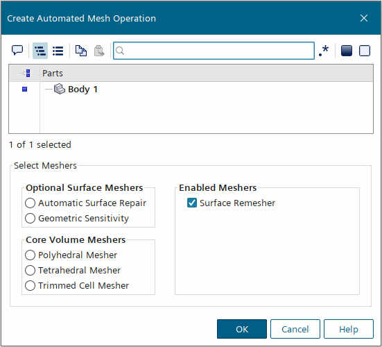
- In the Create Automated Mesh Operation dialog, select the parts you want to mesh and select the appropriate meshers for your application.For meshing shell parts, see Creating Shells from Parts.See Meshers in STAR-CCM+.
 To deselect meshers, deactivate the checkboxes in the Enabled Meshers group box.
 - If you want to generate the mesh using multiple cores, use one of the following techniques:
Parallel Meshing — this technique distributes the simulation domains across nodes. You can generate conformal meshes using this technique. See Parallel Meshing.
To use parallel meshing, select the node and in the Properties window, activate the Enable Parallel Meshing option.
Concurrent Meshing — this technique distributes individual parts to individual nodes, similar to a queuing system on a cluster. You can only generate non-conformal meshes using this technique. You can change the order that parts are meshed to minimize the amount of time it takes to mesh. Concurrent meshing is only available when per-part mode is activated. See Concurrent Meshing.
To use concurrent meshing, select the node and activate the Per-Part Meshing option and set Mesher Execution Mode to .
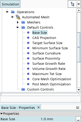
- Expand the node and set appropriate values for Base Size, Target Surface Size, and Minimum Surface Size.
 As a general guideline create a coarse mesh first. You can refine the mesh as needed. To help plan the mesh, use the
 (Measure Distance) tool. See Using the Distance Measuring Tool.
 - Create custom controls to refine the mesh in specific areas of the simulation domain or on specific areas of the geometry. See Creating And Defining Custom Controls. Some common examples are:
- Deactivate prism layers on interfaces.
- Refine the mesh in chosen locations.
- Define precise size controls on some surfaces.
- Permit quad face stretching on wings and blades (anisotropic sizing).
See Custom Mesh Controls.
- Assign the parts to regions. See Regions Layout Workflow.
- Set the boundary types.
- Create a scene to visualize the mesh. See Mesh Visualization.
- Click
 (Generate Surface Mesh) and check the quality of the generated surface mesh. See Checking the Surface Mesh. Alternatively, right-click the node and select Execute Surface Meshers.
 - Make sure to use appropriately sized prism layers in the fluid region. See Prism Layer Mesher.
- If you are fine-tuning the mesh around a particular area of the geometry, or if you are making changes to the geometry design, set up local remeshing. See Local Remeshing.
- Click
 (Generate Volume Mesh). Alternatively, right-click the node and select Execute. In the Output window, check for warnings about surface and volume mesh validity. A valid surface for volume meshing passes the minimum check that the surface mesh is closed, manifold, and contains no self-intersections. This state does not guarantee successful mesh generation or a good volume mesh quality.
 - To make sure the surface is valid, check the Output window for the following message:
Surface is valid for volume meshing - If the volume mesh contains negative volume cells, poor quality cells, or the volume mesh has failed, check the Output window for the following messages:
WARNING: Surface is self-intersecting within machine precision. located at:This warning message provides the location information of a surface which is within floating point precision of itself. When Simcenter STAR-CCM+ detects self-intersecting surfaces, the volume meshing pipeline does not fail; if you find issues with the generated volume mesh, you are advised to review the mesh setup at the reported locations.
Additionally, for the polyhedral and trimmed cell mesher, Simcenter STAR-CCM+ reports isolated surfaces. Tiny undesired isolated surface details may have an adverse effect on the volume mesh quality. You can easily identify and locate such surfaces using the isolated surface diagnostics report. The surface diagnostics report provides the location of disconnected surface patches, for example:
Surface Diagnostics: Isolated surface index: 1, face count: 71296, area: 0.386251, reference location: (-0.00258265 0.0925769 0.1) Total => Surfaces: 1You can control the creation of disconnected surfaces directly in the wrapper by choosing the number of faces in the Smallest Disconnected Surface option. The disconnected surfaces can also be controlled using either the Connected Surface Count Limit or Connected Surface Size Limit(s) property in Automatic Surface Repair.
On prism-growing boundaries, edges with high dihedral angles can introduce undesired definition in the surface and lead to a poor-quality volume mesh. During volume meshing, Simcenter STAR-CCM+ checks for such edges and reports their location in the Output window. The diagnostics report does not include user-defined feature edges, which are carefully treated to produce a good-quality volume mesh.
-
Check the Output window for the following
message:
Dihedral diagnostics is executed for prism growing
                        surfaces only. Special edges are not reported. Dihedral
                        Diagnostics:
This warning message locates the angle range, prism edges and the corresponding number of high dihedral edges. You can easily locate edges with high dihedral angles using the dihedral diagnostics report. For example:
|Angle
                        Range|Prism Edges|High Dihedral Edges|
| 36 - 54 |861 |238 |Furthermore, if edges with dihedral angles greater than the mesher’s threshold are found, the largest five edges are indicated in the following message:
Worst 5 prism growing facetype edges with dihedral
                        angles greater than 46 degrees:
Although the mesh generation process continues regardless of the detected isolated surfaces and high dihedral angles, you are advised to review and resolve any reported surfaces and edges, especially in case of negative volume cells or poor quality cells.
Check the quality of the generated volume mesh. See Checking the Volume Mesh.
Make sure that you check for bad cells. See Identifying and Visualizing Bad Cells.
If the Autosave After Volume Mesh option is activated, Simcenter STAR-CCM+ saves the simulation after generating the volume mesh. See Auto Save Properties.