Creating the FSI Interface
To define the coupling between the fluid and solid region, you create FSI interfaces from the sleeve and fluid geometry part surfaces.
- Expand the node.
- Multi-select the and nodes, right-click one of the selected nodes and select Create Weak In-Place Contact.
- Using the same method, create a weak in-place contact between the and surfaces.
-
Using the same method, create a weak in-place contact between the and surfaces.

- Multi-select the , Inner/Vector Warp.Inner, and Outer/Vector Warp.Outer nodes.
- Right-click one of the selected nodes and select Set New Interface....
- Select the and set Option to Uncoupled.
This setting simplifies the simulation to a one-way coupled setup with the coupling in the structure-to-fluid direction. The fluid load on the sleeve is not considered in the solution.
-
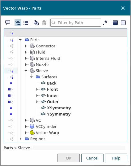
Select the node and check the input parts by clicking Parts property.
In the Vector Warp - Parts dialog, notice that the , Inner and Outer surfaces have been split. Expanding each of the surface nodes reveals two split sufaces, for example, Front[Front/Vector Warp.Front] and Front[rem].

The [Surface][Surface/Vector Warp.[Surface]] represents the faces of the surface that are moved into the interface upon its initialization, based on the Mapped Interface Tolerance. Surface faces that are not within this tolerance are moved out of the interface into the [Surface][rem], it is important to select the parent surface which is the sum of both sets. For more information, see Mapped Contact Interface.
- Save the simulation.