Defining the Fluid Boundaries
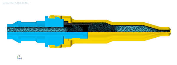
Before you mesh the fluid part, assign the warp surfaces to the relevant fluid boundaries.
To assign the subtracted fluid part to the fluid region:
- Select the node and set Parts to Fluid.
- Expand the node and make sure the part surfaces are assigned to the fluid boundaries appropriately:
Node Property Value Connector Part Surfaces Inlet Part Surfaces MorpherFloating Part Surfaces Nozzle Part Surfaces and NozzleSleeveSection Outlet Part Surfaces Sleeve Part Surfaces Vector Warp XSymmetry Part Surfaces YSymmetry Part Surfaces - Right-click the and select Execute.

- Save the simulation.