Loading the Simulation and Generating the Mesh
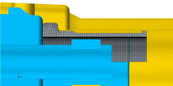
In this tutorial, you are provided with a simulation file that includes the rubber sleeve and nozzle geometry. The file also contains predefined continua, regions, and mesh operations.
To load the initial simulation:
- Launch Simcenter STAR-CCM+ and select
- In the Load a File dialog, click Browse...
- Navigate to the solidStress folder of the downloaded tutorial files.
- Select cleaningNozzle_start.sim and click Open.
- In the Load a File dialog, click OK.
The starting file contains a directed mesh operation which produces a
hexahedral mesh for the rubber sleeve and an automatic polyhedral mesh operation for
the fluid. Additionally, a transform operation adjusts the position of the nozzle to
prevent the nozzle intersecting with the rubber sleeve. In this tutorial you define
two contacts—one for the rubber sleeve and the connector, and one for the rubber
sleeve and the nozzle. The initial tessellation of rigid contact surfaces is very
coarse and is not recommended for contact computation. It is advised to have a
surface mesh of the rigid part similar to the mesh of the deformable part. Therefore
you create a surface mesh operation for rigid contact parts:
- Right-click the node and select .
- In the Create Automated Mesh Operation dialog, select and Nozzle.
- In the Select Meshers box select Surface Remesher.
- Click OK.
- Rename Automated Mesh to Automated Mesh Rigid Contact Parts.
-
Select the Automated Mesh Rigid Contact Parts and set
the following properties:
Node Property Setting Automated Mesh Rigid Contact Parts Per-Part Meshing Activated Perform Proximity Refinement Deactivated Base Size 1.0 mm - Right-click the node and select Reorder...
- In the Reorder Mesh Operations dialog, drag the Automated Mesh Rigid Contact Parts above the Directed Mesh Sleeve, so it is the first operation and click OK.
- Multi-select the Automated Mesh Rigid Contact Parts, Directed Mesh Sleeve, and Transform Nozzle nodes.
- Right-click one of the selected nodes and select Execute.
To visualize the sleeve mesh:
- Open the node.

- Save the simulation as cleaningNozzle.sim.