Creating a Vector Warp for the Sleeve
The rubber sleeve deforms in response to the applied pressure load. To obtain a deformed part, you create a vector warp which deforms according to the computed deformation of the rubber sleeve. The vector warp is useful to obtain the fluid region after the sleeve has deformed.
To create the vector warp:
- Right-click the Derived Parts node and select .
- In the Edit dialog, set the following properties:
Property Value Input Parts Vector Normal Scale Factor 0.0 Display No Displayer - Click Create and Close.
- Right-click the node and select Extract Geometry Part.
The vector wrap is added as a new geometry part.
The surfaces of the vector warp part are independent of each other. As the
vector warp geometry part is created using surfaces that are not connected, the warp
geometry may include defects such as free edges and pierced faces. To detect these
defects:
- Right-click the node and select Repair Surface...
- In the Surface Repair Options dialog, check that Geometry Description is set to Root, then click OK.
-
In the slide out panel on the right-hand side of the Contact
Gap window, select Execute All.
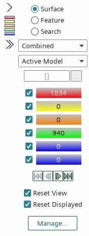
Simcenter STAR-CCM+ detects any errors in the tessellated surfaces of the vector warp part. The part geometry contains 940 free edges and 1834 pierced faces.

- In the Surface Repair panel, click Close.
To prepare the vector warp geometry for meshing, you use the
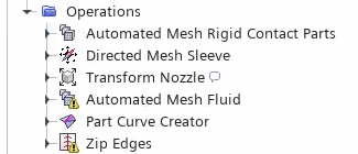
Part Curve Creator and Zip Edges operations
to repair the free edges and pierced faces.
- Right-click the node and select .
-
In the Create Part Curves Creator Operation
dialog, set the following properties and select OK:
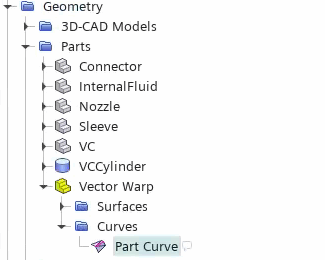
Simcenter STAR-CCM+ adds a Part Curve node under the node.
Property Setting Parts Vector Warp Execute Operation Upon Creation Activated 
- Right-click the Operations node and select .
- In the Create Zip Edges Operation dialog, select the Vector Warp node and click OK.
- Select the node and set Zip Mode to New Description - Discrete.
Simcenter STAR-CCM+ issues a confirmation dialog when you change the zip mode.
- In the Confirm Switch to Description Generating Zip Operation dialog, select Yes.

- Right-click the Zip Edges node and select Execute.
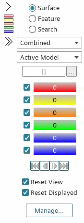
- To verify that the vector warp surfaces have been repaired, open the zip edges description of the Vector Warp in surface repair:
- In the Surface Repair panel, click Close.
- Save the simulation.
