Preparing the Fluid Domain
The internal fluid part does not account for the deformation of the solid sleeve.. To ensure the solid and fluid regions do not overlap, you create a new fluid part by subtracting the internal fluid volume from the deformed vector warp part.
To obtain the fluid geometry:
- Right-click the Operations node and select .
-
In the Create Subtract Operation dialog set
the following properties, then click OK:
Property Value Input Parts - Internal Fluid
- Vector Warp
Target Parts Internal Fluid
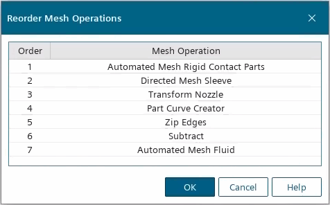
Before executing the operations, you reorder the operations so that Simcenter STAR-CCM+ extracts the fluid geometry before executing the mesh.
- Right-click the Operations node and select Reorder....
-
In the Reorder Mesh Operations dialog, drag
the Automated Mesh Fluid operation below the
Subtract operation, so that it is the last operation
then click OK.

- Right-click the node and select Execute.
- Rename the node to Fluid.
Before executing the mesh, you assign the mesh and custom control inputs:
- Select the node and set Input Parts to Fluid.
- Expand the node and set the following properties:
Node Property Value SleeveInnerAndFront Part Surfaces and Inner. SleeveOuterAndNozzleSleeveSection Part Surfaces - Save the simulation.