Applying the Pressure Load and Remeshing the Fluid
When you apply the pressure load,the rubber sleeve deforms. This deformation results in some fluid mesh cells being squashed or stretched, reducing the mesh quality in this region. To improve the fluid mesh for further analysis, you remesh the fluid region.
To apply a small test load to the sleeve part, you can use the
TestPressure pressure load provided within the starting
simulation.
- Select the node and set value to 0.1 bar.
- To apply the pressure load, click
 (Step).

In the scene, you can view the rubber sleeve in its original undeformed
state before the pressure load is applied by setting Relative or
Absolute Coordinates to Absolute:
-
Select the node, and set Relative or Absolute
Coordinates to Absolute.

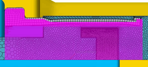
The highlighted vector warp part is associated with the Volume Mesh representation and not tied to the deformed rubber sleeve.
Before you remesh the fluid, reset the vector warp coordinates
and update the vector warp part:
- Select the Vector Warp node, and set Relative or Absolute Coordinates to Relative
- Right-click the node and select Update.
To remesh the fluid:
-
Right-click the node and select Execute All.
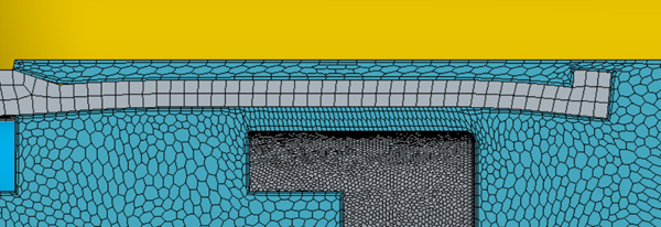
Once the Part Curve Creator, Zip Edges, and Subtract operations are executed, the Sleeve and Fluid geometry parts are updated with the deformed sleeve geometry. The Automated Mesh Fluid remeshes the fluid region. The resultant mesh no longer contains any deformed cells.

-
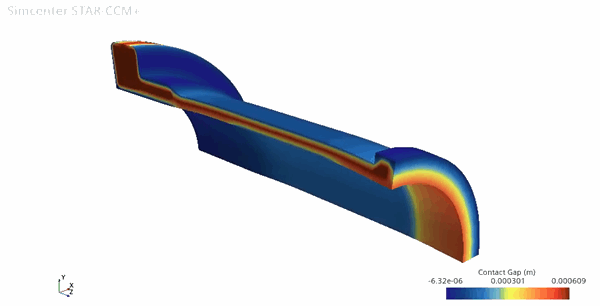
To visualize the contact gap on the deformed sleeve, open the
Contact Gap scalar scene and align the part as
shown:
