Mixing Plane Interface
The mixing-plane interface type is used to compute steady-state simulations of multi-stage turbomachinery flows.
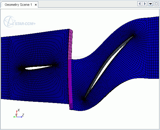
This interface makes it possible to simulate the flow across stages with different pitches moving relative to one another. At the interface, circumferentially averaged flow field data is transferred between two rotationally periodic regions. These regions must be of the same continuum, and aligned on the same axis. The mixing plane interface type is available on indirect interface topologies only.
The mixing-plane interface allows the transfer of mass, momentum, energy, and other quantities across the interface using a circumferential averaging technique. The values to be transferred across the interface are averaged in concentric, circumferential rings, or bins, of uniform radial thickness, covering the entire span and pitch of the boundary. Due to the circumferential averaging, the final solution is characterized by radially varying profiles of flow field quantities that remain uniform across the pitch within any given circumferential bin.

The parts-based mixing-plane interface only allows one contact.
A mixing-plane interface cannot be used in combination with multi-component VOF phases. Simcenter STAR-CCM+ supports the use of mixing-plane interfaces with single-component VOF phases only.
Mixing-plane interfaces can be used with the Eulerian Multiphase model. However, a mixing-plane interface cannot be used in combination with granular flow models.
Mixing plane interfaces are also compatible with the Two-Phase Thermodynamic Equilibrium model. This model is particularly useful for the simulation of Low Pressure (LP) turbines where wet steam needs to be considered. The current compatibility is limited to the implicit mixing-plane solution approach.
Implicit vs. Explicit Mixing-Plane Solution Approaches
The solution across the mixing-plane can be computed using either an implicit or an explicit approach.
In the implicit mixing-plane approach, the cells on either side of the interface are directly connected through each circumferential bin. The approach introduces additional degrees of freedom to the linear system – one additional degree of freedom per variable per circumferential bin. These degrees of freedom represent the conservation of fluxes across the faces composing either side of a given bin. In this way, solution of the linear system results in implicit updates to circumferentially averaged values on either side.
The implicit mixing-plane approach is available with the Coupled Flow model, the Segregated Flow model, and the Harmonic Balance Flow model. The Harmonic Balance model supports the implicit mixing plane approach only when the number of modes is set to zero, that is, when the Harmonic Balance solver is used only to compute the time-mean solution.
The explicit mixing-plane approach closely follows the procedure used in the Non-Reflecting Boundary Condition. Here, updated values on the interface boundaries are computed directly, based on those from the previous iteration. As in the Non-Reflecting Boundary Condition, all outgoing waves pass through the interface without reflection. Circumferential averaging of conserved quantities, combined with piecewise constant interpolation between bins in the radial direction, is used to prescribe the zero-th mode solution required by the non-reflecting boundary condition.
The explicit mixing-plane approach is available in combination only with the Coupled Flow model or the Harmonic Balance Flow model. See [169], [170], [171] and [208].

Mixing Plane Interface Properties
You can use the properties that are listed below to adjust the specifications of a Mixing Plane Interface node.
- Boundary-0
- Indicates the "fixed" side of the interface (Read Only).
- Boundary-1
- Indicates the "adapted" side
of the interface (Read Only).
Vertices from boundary-1 are projected onto boundary-0. The orientation can be swapped through the right-click action Reverse Orientation.
- Type
- Defines the type of interface. Must be set to Mixing Plane Interface.
- Topology
- Defines the connection type between the interfaces. Only the Indirect type is possible.
- Connectivity
- Defines how the boundaries on two sides of the interface are connected. Mixing Plane interfaces have the connectivity type Connect Average, which is automatically assigned when mixing plane interfaces are created.
- Allow Per-Contact Values
- Allows you to define the interface tolerance
individually for each contact. Activates the child property Specify by Part Subgroup.
注 This property is only valid for contact-mode boundary interfaces. See also: Contact-Mode Boundary Interfaces.
Mixing Plane Interface Conditions
You can use the properties that are listed below to adjust the specifications of a Physics Condition interface node. You can specify either explicit or implicit methods.
- Connectivity Option
-
- Option
- Provides energy source options for the interface.
- Implicit
- Uses the implicit mixing plane approach. Available with Coupled Flow, Segregated Flow and Harmonic Balance Flow models. This is the default.
- Explicit
- Uses the explicit mixing plane approach. Activates the child node Mixing Plane Option. Available with Coupled Flow and Harmonic Balance Flow models.
- Mixing Plane Option
-
- Option
- Activates or deactivates the non-reflecting boundary condition
at mixing-plane interface boundaries. Available only with the
Coupled Flow model, when Connectivity
Option is set to Explicit. When the Harmonic
Balance Flow and Energy model is active, the
Connectivity Option is always set to
Explicit and the non-reflecting
boundary conditions always applies at the mixing plane
interface.
- None
- Deactivates the non-reflecting boundary condition at mixing-plane interface boundaries. Circumferentially averaged conserved quantities at each radial location prescribe the boundary condition at the two interface boundaries belonging to the mixing plane interface.
- Non-Reflecting
- Activates the non-reflecting boundary condition at mixing-plane interface boundaries. Circumferential averaging of conserved quantities, combined with piecewise constant interpolation between bins in the radial direction, prescribe the zero-th mode solution required by the non-reflecting boundary condition. The higher modes are treated using the non-reflecting boundary condition that allows the outgoing waves to pass through the mixing plane without reflecting back into the computational domain. This setting is the default.
Mixing Plane Interface Field Functions
The following field functions become available when the mixing plane interface is used:
 BCB_dTheta
- Displays the change in the tangential coordinate across each cell face of the bin. When the mesh is structured, the sum of BCB_dTheta for all the cell faces of the bin is equal to the pitch of that bin.
 Boundary Circumferential Bin
Coordinate
Boundary Circumferential Bin
Coordinate- This coordinate varies from the hub to the shroud of the boundary. It is a constant across all the cell faces of a bin. This coordinate is computed as a blend of axial and radial coordinates. It is equal to the radius of the bin when the machine axis is aligned with the boundary normal, and is equal to the axial coordinate when the machine axis is perpendicular to the boundary normal.
 Boundary Circumferential Bin
Index
Boundary Circumferential Bin
Index- Displays the sequential index number of the bin.
 Boundary Circumferential Bin
Pitch
Boundary Circumferential Bin
Pitch- Displays the change in the tangential coordinate across the periodic boundaries, as measured in the bin.
 Boundary Circumferential Bin
Spatial Modes
Boundary Circumferential Bin
Spatial Modes- Displays the number of spatial Fourier modes considered in this bin, used to compute the solutions for those modes.
 Boundary Circumferential Bin
Theta
Boundary Circumferential Bin
Theta- Displays the tangential coordinate, measured in the bin.