Fluid-Structure Interaction General Workflow
Starting from an uncoupled set up with a fully defined fluid and solid domain, Simcenter STAR-CCM+ allows you to defined a general FSI problem.
-
Create the fluid-structure interface as a contact-mode interface (see Defining the Regions Layout).
Boundary-mode interfaces are not supported as fluid-structure interfaces. By default, the Fluid Structure Coupling solver enforces the use of compatible settings (see Model Compatibility). If you run an FSI simulation with a boundary-mode fluid-structure interface, Simcenter STAR-CCM+ stops the simulation and issues a warning.
- If you wish to continue the simulation despite the incompatible interface type, select the node and set Model Compatibility to Ignore.
-
Make sure that the interface type is set to Mapped Contact
Interface. To set this type, select the relevant node and set Type to Mapped
Contact Interface.
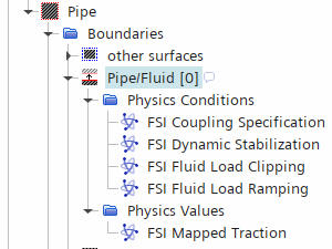
Simcenter STAR-CCM+ detects the fluid/solid interface and adds FSI controls under .

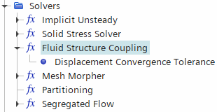
As well as adding FSI control, Simcenter STAR-CCM+ adds the Fluid Structure Coupling solver to the Solvers node.
For two-way coupled problems you are strongly advised to use a
stabilization method. As well as stabilizing the solution, the stabilization method
accelerates the convergence of the coupled system.
-
Apply one of the two stabilization methods available:
- For transient simulations with large displacement of fluid
volume, select Dynamic:
- Select the node and set Stabilization Method to Dynamic.
- Select the node and set the Method to either Automatic or Manual.
- If Method is set to Manual, select and set Dynamic Coefficient to your chosen value. For example, for water flow in a slender pipe, the displaced fluid volume per unit area can be estimated as half the pipe inner diameter.
- For steady simulations or simulations in which the
displaced fluid volume is negligible, select Constant Displacement
Under-relaxation:
- Select the node, and set Stabilization Method to Constant Displacement Under-relaxation.
- Select the Constant Displacement Under-relaxation node, and set the Under-Relaxation Factor value.
If you select a stabilization method that is not appropriate to your setup (for example, you select the Dynamic in a steady simulation), Simcenter STAR-CCM+ resets the Stabilization Method to None. - For transient simulations with large displacement of fluid
volume, select Dynamic:
-
Select the node, and set Option to one of the
following:
- For one-way fluid-to-structure and two-way coupled problems — Fluid Load - Pressure and Wall Shear Stress (default).
- For pressure dominant one-way fluid-to-structure and two-way coupled problems — Fluid Load - Pressure
- For wall shear stress dominant one-way fluid-to-structure and two-way coupled problems — Fluid Load - Wall Shear Stress
- For uncoupled problems — Uncoupled.
The fluid region FSI Coupling Specification is a read-only property and is controlled by the motion of the coupled solid region (see FSI Region Motions).
As outlined in the FSI Solution Strategy, Simcenter STAR-CCM+ allows you to configure the force consistency
through the ramping and clipping of the fluid traction.
-
If you wish to set ramping:
- Select the node and set Option to Linear.
- Select the node, and use the Starting Time and Stopping Time properties to set the ramping duration.
注 You must set the Stopping Time before you set the Starting Time property. -
If you wish to set clipping:
- Select the node and activate the Pressure, Shear, or Pressure and Shear properties.
- Select the or FSI Shear Clipping node and set the Minimum and Maximum values.
-
Expand the node and define the motion of the fluid and solid regions.
- For the solid region, you can define it as
Stationary, or apply a rigid motion (such as
Translation or
Rotation), a Solid
Displacement motion (which accounts for the solid
deformation), or a superposition of rigid motions and Solid
Displacement.
Only include the Solid Displacement motion when modeling the effect of the solid deformation on the fluid. If you do not include the solid displacement motion, the Solid Displacement is still computed by not applied to the coordinates of the solid.
- For the fluid, you can define it as Stationary, apply rigid motions, or use the Morphing motion. The Morphing motion adjusts the fluid mesh based on the solid motion and/or deformation.
[Fluid Region] Motion [Solid Region] Motion Scenario Stationary or Prescribed Rigid Motion Stationary or Prescribed Rigid Motions Any simulation where you neglect the effects of the structure on the fluid. The rigid motions of the fluid and solid regions must be consistent. Morphing Stationary or Prescribed Rigid Motions Any simulation which neglect the effect of the structural deformation on the fluid, but takes into account the effect of any rigid motion of the structure. Morphing Solid Displacement+ any prescribed rigid motions Any simulation that takes into account the effects of the solid deformation on the fluid. This includes both one-way structure-to-fluid problems and two-way coupled problems. - For the solid region, you can define it as
Stationary, or apply a rigid motion (such as
Translation or
Rotation), a Solid
Displacement motion (which accounts for the solid
deformation), or a superposition of rigid motions and Solid
Displacement.
To assign the motions to the fluid and solid regions:
-
Select the node and node, and set Motion to the motions you defined for
the fluid and solid under the node.
If you change the to Stationary, the Reset Mesh option is not available in the Clear Solution dialog. For more information, see Reset Mesh.
-
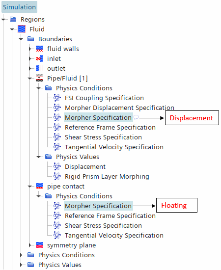
When morphing the fluid, for cases where the fluid boundary is not entirely
mapped to the fluid-solid interface, set the morphing method for the unmapped
boundary as follows:
-
Set the Mesh Morpher solver properties:
- Select the node and activate Morph At Inner Iterations. When enforcing compatible settings (see Model Compatibility for Fluid Structure Coupling), deactivating this property results in an error.
- To improve performance, you can activate Boundary Layer Morphing. However, this may come at the cost of accuracy in the fluid solution.
To prevent the FSI simulation from stopping after the first inner
iteration, you must disable the global force and displacement stopping
criteria.
- Within the Stopping Criteria node, multi-select the Force Criterion and Displacement Criterion nodes, and deactivate Enabled.
