耦合 DFBI 体

DFBI 体耦合定义体-体和体-环境耦合元素。共有 6 种预定义耦合类型和一种用户自定义耦合类型。

要定义 DFBI 耦合:
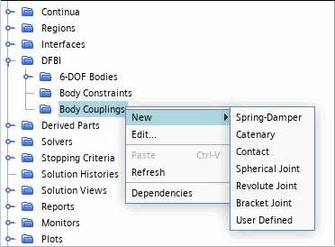
  1. 右键单击 DFBI > 体耦合节点,然后选择新建
  2. 选择以下某一耦合类型,然后设置相应的属性:


    耦合类型 6 自由度体维度 体运动选项
    Spring-Damper Coupling 2D 或 3D 所有
    Catenary Coupling 2D 或 3D 所有
    Contact Coupling 2D 或 3D 所有
    Spherical Joint Coupling 3D 多体运动
    Revolute Joint Coupling 3D 多体运动
    Bracket Joint Coupling 3D 多体运动
    User-Defined Coupling 2D 或 3D 所有
还可以设置用户自定义体耦合。此类型用于以用户自定义方式将体耦合到另一个刚体或环境。用户自定义的耦合包含两个端点。通过场函数、表或用户程序来定义这些端点处作用的力和力矩。例如,可以使用此功能将 Simcenter STAR-CCM+ DFBI 模拟耦合到第三方系泊动态 API。
  1. 右键单击 DFBI > 6 自由度体 > 体耦合节点,然后选择新建 > 用户自定义
    以下节点会添加到模拟树:
    • 体耦合 > 用户自定义 1
    • 6 自由度体 > [体 1] > 外力与力矩 > 用户自定义耦合力[用户自定义 1]
    • 点集合 > DFBI 点集合[用户自定义耦合 1]

    用户自定义耦合自动创建包含两个点的点集合。这两个点表示耦合端点。可以使用点集合访问端点处定义的数据或对场景中的端点进行可视化。

  2. 选择体耦合 > 用户自定义 1 节点,然后指定要耦合的对象:
    1. 对象 1对象 2 设为先前定义的刚体或环境
    2. 要指定耦合附着点的位置,输入位置 1位置 2 的坐标。
    有关所有属性的描述,请参见User-Defined Coupling
  3. 要定义作用于耦合终点的力和(可选)作用于体位置的附加力矩,选择用户自定义 1 > 力分布节点,然后将方法设为某一通用选项。
  4. 要通过场函数或用户编码定义力分布,可使用用户自定义耦合的特定场函数。请参见用户自定义耦合场函数。如果将方法设为用户程序
    1. 为采用 C、C++ 或 Fortran 的用户编码创建源程序。
      下面显示了用户自定义法的编码示例。第一个文件 uclib.c 定义两个函数来计算从 Simcenter STAR-CCM+ 调用的力和力矩:
      #include "uclib.h"
      
      void calculateForce(Real*, int, CoordReal*, unsigned int*, CoordReal*);
      void calculateMoment(Real*, int, CoordReal*, unsigned int*, CoordReal*);
      
      void
      USERFUNCTION_EXPORT uclib()
      {
        /* Register user functions here */
        ucfunc(calculateForce, "PointSetProfile", "Calculate Force");
        ucarg(calculateForce, "Point", "Coord", sizeof(CoordReal[3]));
        ucarg(calculateForce, "Point", "BodyId", sizeof(unsigned int));
        ucarg(calculateForce, "Point", "BodyPosition", sizeof(CoordReal[3]));
      
        ucfunc(calculateMoment, "PointSetProfile", "Calculate Moment");
        ucarg(calculateMoment, "Point", "Coord", sizeof(CoordReal[3]));
        ucarg(calculateMoment, "Point", "BodyId", sizeof(unsigned int));
        ucarg(calculateMoment, "Point", "BodyPosition", sizeof(CoordReal[3]));
      }

      以下用户程序对耦合端点之间作用的弹簧进行建模。一个端点附加到体,另一个端点附加到环境或另一个体。

      #include "uclib.h"
      
      void USERFUNCTION_EXPORT
      calculateForce(Real (*result)[3], int size, CoordReal (*position)[3], 
        unsigned int *bodyId, CoordReal (*bodyPosition)[3])
      {
        CoordReal delta[3];
        Real stiffness = 20.;     /* Spring stiffness */
        int i, j;
      
        if (size != 2)    /* If the number of end points is unequal 2, do not execute the following coding. */
                          /* This if-block is essential for parallel simulations. The DFBI point */
      		    /* set is filled with the two end points on the master node only. */
      
          return;
      
        for (j = 0; j < 3; ++j)   /* Compute force vectors at the end points */
        {
          delta[j] = position[1][j] - position[0][j];
          result[1][j] = -stiffness*delta[j]; /* Force at second end point */
          result[0][j] = -result[1][j];   /* Force at first end point */
        }
      }
      
      void USERFUNCTION_EXPORT
      calculateMoment(Real (*result)[3], int size, CoordReal (*position)[3], 
        unsigned int *bodyId, CoordReal (*bodyPosition)[3])
      {
        int i, j;
      
        for (i = 0; i < size; ++i)
          for (j = 0; j < 3; ++j)
            result[i][j] = 0.;    /* Calculate no additional moment. */
      }
    2. 创建新用户库
    3. 将用户库加载到 Simcenter STAR-CCM+ 中。
    4. 选择力分布节点,然后将函数设为 [您的用户编码]
      对于此示例:选择力分布节点,然后将函数设为计算力
    有关详细信息,另请参见力分布属性
  5. (可选)要定义额外力矩,重复上一步,但改为编辑力矩分布节点。
    有关详细信息,另请参见力矩分布属性
  6. 要在场景中可视化用户自定义耦合,将点集合 > DFBI 点集合[用户自定义耦合 1] 添加至显示器。
    在场景中,耦合仅由其端点表示。Simcenter STAR-CCM+ 不知道哪一个是用户自定义的实际耦合(基于定义)。可以访问演示组 User Defined DFBI Couplings(用户自定义 DFBI 耦合) 中收集的一些特定场函数,并将它们应用于场景中的标量或矢量显示器,还可应用于报告或表达式。