Setting Boundary Conditions

You set the initial conditions for the Pressure, Velocity, and Volume Fraction as well as the boundary conditions for the regions.

You define the side and bottom boundaries of the main fluid domain as Velocity Inlets and the top boundary as a Pressure Outlet. On the side boundaries, you apply the VOF Wave Forcing Boundary Option, which enforces a simplified solution on the outer boundaries and prevents wave reflection.
  1. Expand the Regions > Domain > Boundaries node and set the following properties:
    Node Property Setting
    • Bottom
    • Front
    • Rear
    • Left
    • Right
    Type Velocity Inlet
    Top Type Pressure Outlet
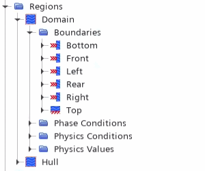

  2. Select the Domain > Physics Conditions > VOF Wave Zone Option and set VOF Wave Zone Option to Forcing.
  3. To set the VOF Wave Forcing Length:
    1. Select the Physics Conditions > Forcing Length Specification node and set Length Specification Option to Boundary.
    2. Select the Physics Values > Forcing VOF Wave Specification and set VOF Wave to Linked Vof Wave 1.
  4. To set the velocity and wave forcing specification for the boundaries:
    1. Multi-select all the boundaries under Domain > Boundaries.
    2. Right-click one of the selected boundaries and select Edit.
    3. In the Multiple Objects dialog, select Expand/Contract Values.
    4. For all boundaries except Top, expand Physics Conditions > Velocity Specification and set Method to Components.
    5. For all boundaries except Top and Bottom, expand Physics Conditions > VOF Wave Forcing Boundary Option and set Method to Yes.
    6. For all boundaries except Top and Bottom, expand Physics Values > VOF Wave Forcing Length and set Value to ${Wavelength}.
  5. To set the volume fraction, turbulence, and pressure for the domain:
    1. With the Multiple Objects dialog still open, for all boundaries, set the following properties:
      Node Property Setting
      Turbulence Intensity Value 1.0E-5
      Turbulent Viscosity Ratio Value 1.0E-4
    2. For all boundaries expand the Volume Fraction node and set Method to Composite N-1.
    3. For all boundaries, expand the Volume Fraction > Composite N-1 > Water node and set the following properties:
      Property Setting
      Method Field Function
      Value Vof Waves > Linked VOF Wave 1 > Volume Fraction of Heavy Fluid of Linked Vof Wave 1
    4. For the Bottom, Front, Left, Rear and Right boundaries, set the following properties:
      Node Property Setting
      Velocity Method Field Function
      Vector Function Vof Waves > Linked VOF Wave 1 > Velocity of Linked Vof Wave 1
    5. For the Top boundary, set Pressure to the following:
      Property Setting
      Method Field Function
      Value Vof Waves > Linked VOF Wave 1 > Hydrostatic Pressure of Heavy Fluid of Linked Wave 1
  6. Save the simulation.