Defining the Motion of the Hull as a 6-DOF Body

The hull is a rigid body that moves at a constant velocity of 8 knots. In addition to the prescribed motion, the hull moves in response to the force exerted by the surrounding fluid.

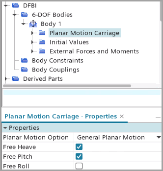
To combine the DFBI motion with the prescribed forward motion, you create a 6-DOF body with a planar motion carriage, which simulates a captive motion in the X-Y plane of the Laboratory coordinate system. Specially, you define the trajectory on the X-Y plane, while allowing the body to move freely in the direction of heave (translation along the Z-axis), pitch (rotation around the Y-axis), and roll (rotation around the X-axis). The boat's trajectory is 8 knots * time in the X direction, 0.0 in the Y direction.
  1. The velocity of a boat is typically measured in knots. To add new units in Simcenter STAR-CCM+:
    1. Right-click the Tools > Units node and select New > Units.
    2. Rename Units_1 to Knots.
    3. Set the following properties:
      Property Setting
      Conversion 0.514444
      Dimensions Velocity
  2. For convenience, create a parameter for the speed of the hull:
    1. Right-click the Automation > Parameters node and select New > Scalar.
    2. Rename the Scalar node to Speed.
    3. Set the following properties:
      Property Setting
      Dimensions Velocity
      Value 8 Knots
  3. To define the 6-DOF body, first assign a DFBI motion model to the fluid region containing the hull boundary:
    1. Right-click the Tools > Motion node and select New > DFBI Rotation and Translation.
    2. Select the Regions > Hull > Physics Values > Motion Specification node and set Motion to the created DFBI Rotiation and Translation.
  4. To define the 6-DOF body:
    1. Right-click the DFBI > 6-DOF Bodies node and select New Body > 3D > Continuum Body.
    2. Select Body 1 and set the following properties:
      Node Property Setting
      Body 1 Body Surface Subtracted Hull
      Body Mass 1.77E7 kg
      Body Motion Option Planar Motion Carriage
      Planar Motion Option Planar Motion Option General Planar Motion
      Free Heave Activated

      Translation in the X axis is allowed in the body coordinate system.

      Free Pitch Activated

      Rotation around the Y axis is allowed in the body coordinate system.

      Free Roll Deactivated

      The simulation is symmetrical around body X axis - the roll is zero. To avoid numerical noises, roll motion is deactivated.

      General Planar Motion Translation X ${Speed}* ${Time}

      All other trajectory components are set to zero.

      Translation Y 0.0 m

      No translation in the Y direction is allowed in the laboratory coordinate system.

      Rotation Z 0.0 radian

      No rotation around the Z direction is allowed in the laboratory coordinate system.

      User Defined Derivatives Activated

      Uses explicitly the first and second-order time derivatives to compute the user-defined trajectory.

      Planar Motion Derivatives Velocity X ${Speed}

      All other velocity components are set to zero.


To simplify the initial value setup of the 6-DOF body, you create an initial body coordinate system with the origin at the center of gravity of the body and the axes reflecting the initial orientations of the body.
  1. To create an initial body coordinate system:
    1. Right-click the Tools > Coordinate Systems > Laboratory > Local Coordinate Systems > New > Cartesian and accept the default values in the Create Cartesian Coordinate System dialog.
    2. Click Create.
    3. Rename Cartesian 1 to InitialBodyCoordinateSystem.
    4. Select the InitialBodyCoordinateSystem node and set Origin to [90.0, 0.0, 0.0] m,m,m.
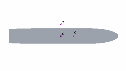
      A local coordinate system at the center of gravity of the boat is created:


  2. Select the Body 1 > Initial Values node and set the following properties for the 6-DOF body:
    Node Property Setting
    Attachment Point Coordinate System Laboratory → InitialBodyCoordinateSystem
    Position [0.0, 0.0, 0.0]

    Specifies the position where the body is initially attached to the planar motion carriage. In this case, the attachment point is the center of mass of the body.

    Center of Mass Coordinate System Laboratory → InitialBodyCoordinateSystem
    Position [0.0, 0.0, 0.0]
    Moment of Inertia Coordinate System Laboratory → InitialBodyCoordinateSystem
    Diagonal Components [3.0E9, 4.0E10, 4.0E10]
    Orientation Coordinate System Laboratory → InitialBodyCoordinateSystem
  3. Select the Body 1 > External Forces and Moments node and make sure that Gravity Force is activated.
  4. Save the simulation.