Define the Morphing Motion
Set up mesh morphing around the blade regions so the mesh updates based on the beam displacements imported from the external motion file.
- Expand the Regions node and multi-select the Blade 1, Blade 2, Blade 3, and Blade 4 regions.
- Right-click one of the selected regions and select Edit....
- In the Multiple Objects dialog expand and set Motion to Morphing.
- Click Close.
- Expand the Boundaries node for each blade region and multi-select all four Blade boundary nodes.
- Right-click one of the selected boundaries and select Edit....
-
In the Multiple Objects dialog, set the
following properties:
Node Property Value Physics Conditions  Morpher Specification
Specification Displacement Morpher Displacement
SpecificationSpecification Total Physics Values Morpher Rigid Boundary
MotionRigid Motion Rotation Morpher Total Linear
DisplacementMethod Field Function Vector Function - Click Close.
-
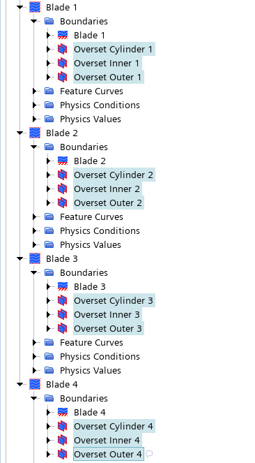
Expand the Boundaries node for each blade region and
multi-select the Overset Cylinder, Overset Inner, and Overset Outer
boundaries.
- Right-click one of the selected boundaries and select Edit...
-
In the Multiple Objects dialog, expand and set Specification to
Floating.
By setting the morpher specification to Floating, you define the morphing such that the overset boundaries move according to the interpolation of the displacement vector describing the blade boundaries morphing. Hence, the overset regions will morph along with rotation motion of the blades.
- Click Close.
-
Expand the Interfaces node. For each Overset
Mesh, expand the Physics Conditions node.
Multi-select all four Overset Hole Cutting Options and
enable Alternate Hole Cutting.
The Alternate Hole Cutting approach is a more robust method when running on many cores.
- Multi-select all four of the external beam regions under the Regions node (Beam 1, Beam 2, Beam 3, and Beam 4).
- Right-click one of the selected regions and select Edit....
- Expand and make sure Motion is set to Rotation.
- Click Close and save the simulation.