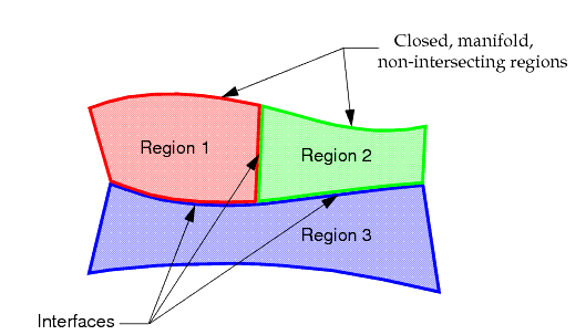
Multi-Region Surface Requirements
- each region must be closed, manifold, and non-intersecting
- boundaries that exist between regions must be grouped and flagged as interfaces

TheSurface Remesher can automatically produce a conformal mesh across an in-place interface containing mismatched boundaries. To do this, Simcenter STAR-CCM+ imprints one boundary on the other so that a mapped boundary surface is produced, resulting in a conformal triangulation. For a case such as that above, use a single mesh to mesh all regions in order to ensure that a conformal surface and volume mesh is produced at interfaces.
In instances when a conformal volume mesh is not required between each region, then the requirement to have interfaces and imprints defined is relaxed. In this case, you can mesh each region independently using different mesh operations. The meshes can later be joined back together either by using an in-place interface or by fusing the boundaries. In some respects, this approach is far easier than ensuring that the region interfaces and imprints are properly defined. However, the process results in increased overhead at the simulation stage, due to the extra interface information that is stored and the extra face divisions in the boundary fusing process.
- the format that is used to export the CAD data, for example, STL, IGES, VDA
- whether each part in the assembly is exported to the same file or to separate files
- whether duplicate surfaces exist at inter-region boundaries
- whether inter-region surfaces have been imprinted or not
- whether the assembly contains all relevant fluid/solid parts or only the solid material portion of the geometry.
For example, certain CAD packages such as SolidWorks allow you to save an assembly as a single STL file or each part as a separate STL file. Similarly, in most CAD packages, you can elect to open parts individually and save them as separate IGES files or other format. Alternatively, the entire assembly can be saved to a single file, which is usually the default (or only option allowed). Depending on the method that is used to save the import file or files, inter-region boundaries can have either single or duplicate surfaces, which do not necessarily have identical perimeter triangulation. Additionally, some CAD packages allow imprinting (whereby one part can be “stamped” onto another, leaving an edge definition that represents the common area) while others do not have this feature. Finally, the assembly typically only represents the solid material, rather than the fluid volume that is required for CFD simulations. Some CAD packages easily allow the fluid portion to be extracted and combined back into the assembly while others do not. In summary, many different factors influence the level of effort that is required to prepare the import geometry for Simcenter STAR-CCM+.
- create a (duplicate) interface boundary
- create a new region from a collection of boundaries.
Being able to create a duplicate boundary at an inter-region interface allows two regions that were previously “joined” to be separated out, allowing a new region to be created from individual boundaries. The surface boundary that was duplicated maintains an in-place interface definition as part of its make up so no further action is required once the region has been redefined.
The use of the in-place interface option is important for defining the surface correctly in cases where regions are defined at import but no connectivity information between regions is included. By including an in-place interface, conformal meshes at interface boundaries can be created for the surface and volume meshers.
- the CAD import results in a single region
- the CAD import results in multiple regions.